GUI Guide
Fierro can be run in a terminal using the command line interface or by using the graphical user interface (GUI).
The Fierro GUI can run on Linux, Mac, and Windows (inside WSL-2) machines. Note: if you are running any of the graphical user interfaces through WSL on windows, you may need to install and run an "X Server" on your Windows side to connect the WSL applications to the display. For testing, we use VcXsrv. Once the X server is running on Windows, you can connect your WSL terminal application to the display by setting the DISPLAY environment variable:
export DISPLAY=localhost:0.0Fierro GUI
The Fierro GUI is a Python based user interface that integrates with paraview to render initial conditions and results. The recommended way to use the gui is through the anaconda package "fierro-gui" available on our package repository. For more detailed installation instructions, see our installation guide.
Once the Fierro GUI is installed, it can be launched by running the fierro-gui command. The instructions that follow will
guide a user through the steps to run the EVPFFT solver from the GUI.
1. Importing a Part
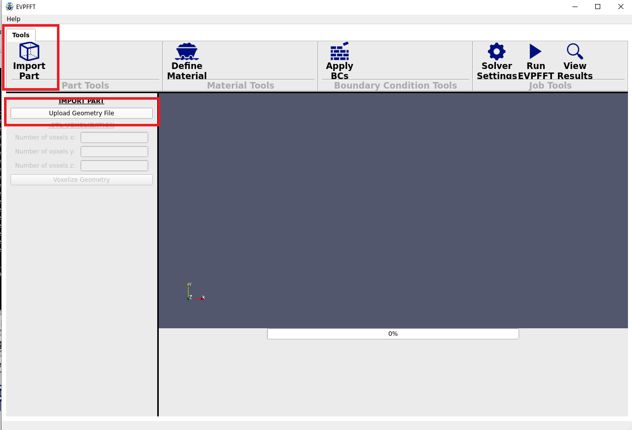
The first step to running EVPFFT is importing a part geometry for analysis. EVPFFT operates on a voxelized grid, however the GUI requires a triangle mesh in a binary STL format and will do the necessary voxelization automatically. To import a part, click the "Import Part" button followed by the "Upload Geometry File" button and select the input STL file.
2. Voxelization
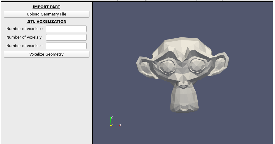
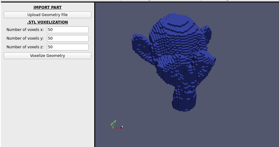
After selecting your part, you should see the STL rendered in the right window. From here, you can voxelize it at the desired resolution. Be aware that your mesh might look like it is scaled differently along X, Y and Z after voxelization, however, this is just a visual artifact of the voxelization process.
3. Material Properties
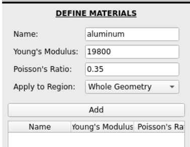
Once you have your geometry loaded, you can specify the relevant material properties in the "Define Material" tab. Currently we support specifying the Young's Modulus and Poisson's Ratio for the material. Currently the application supports one material applied to the whole geometry, but more advanced options will likely be available in the future.
4. Boundary Conditions
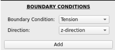
To complete your problem definition, you need to specify along which axes tension will be applied under the "Boundary Conditions" tab.
5. Solver Settings (Optional)
Initially, it is recommended to ignore the solver settings. If you see that your results are not converging properly, then you may need to tweaking the options here.
6. Run and View Results
Running
Lastly, you can "Run EVPFFT" and view the results. While it is running, intermediate status output will be displayed in the lower panel along with the progress bar. Depending on your voxel resolution and hardware, this could take some time to finish.

Results
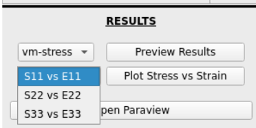
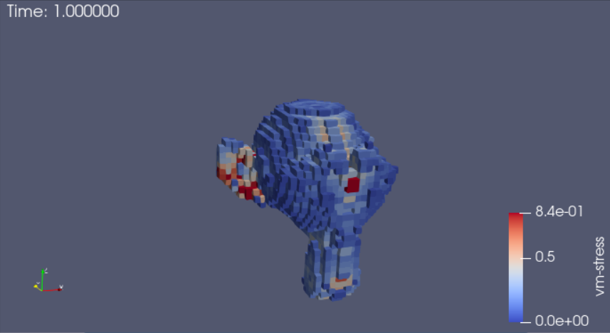
Once the process is complete, you can view some results the results directly in the GUI, or open them in ParaView for more detailed analysis. Within this application, you can view the stress strain curves or examine a 3D render of your voxelized mesh with strain or stress color coding.
More features coming soon...