QUADXY
Define an arbitrary, logical quad of points in 3D space with NDIM1 x NDIM2 number of nodes.
The four corners of the quad surface are defined in counter clockwise order ( the normal to the quad points is defined using the right hand rule and the order of the points).
The nodes can be connected using the createpts/brick/xyz command.
SYNTAX
quadxy/ndim1, ndim2 /x1,y1,z1/x2,y2,z2/x3,y3,z3/x4,y4,z4
EXAMPLES
# create quad sheet
define NX 3
define NY 5
cmo/create/moquad/ / / quad
quadxy/ NX NY /0. 0. 0./10. 0. 0./10. 20. 0./0. 20. 0.
createpts/brick/xyz/ NX NY 1 /1,0,0/connect

# read elevations from data file with x y z coordinates
# save z to attribute named elev and set to 0 same as template
cmo / create/ motmp
cmo readatt motmp /xic,yic,zic/1,0,0/ ev_points.dat
cmo/addatt/motmp/ elev/VDOUBLE/scalar/nnodes/linear/permanent/
cmo/copyatt/ motmp motmp/ elev zic
cmo/setatt/ motmp / zic 0.

# assign the z values from the point data to the template
interpolate/voronoi/moquad zic/1,0,0/ motmp elev
cmo/printatt/moquad/ zic minmax
dump/avs/ quad_surface.inp/ moquad
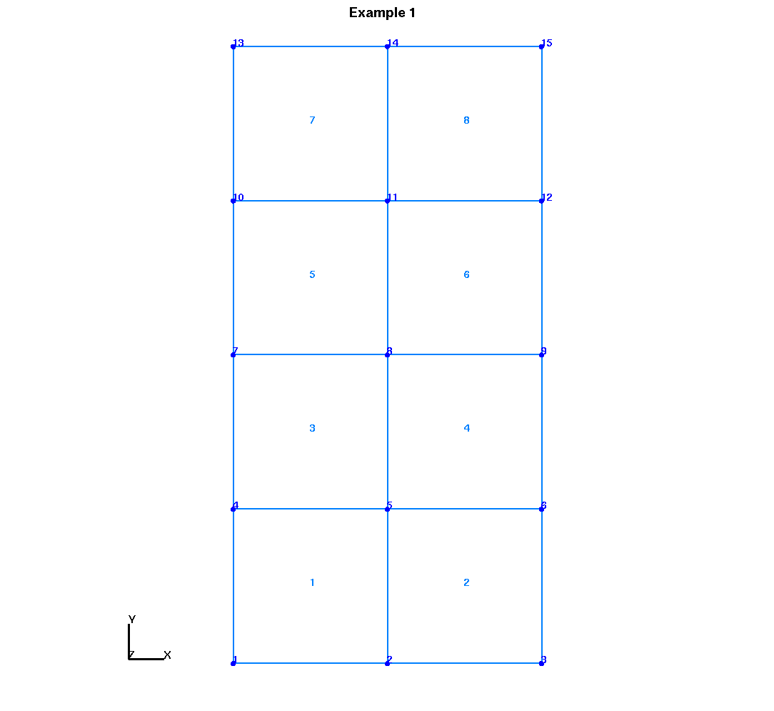
This is XY Flat, as shown in first image, a 3 x 5 quad grid on the XY plane where Z = 0. Next, this example shows how point data can then be copied into this quad template. It is important that the quadxy template and the point set have the same NX NY. But node order does not matter as interpolate will assign elevation from nearest node.
define X1 2.0
define Y1 40.0
define Z1 4.0
define X2 2.0
define Y2 1.0
define Z2 1.0
define X3 50.
define Y3 20.
define Z3 40.
define X4 55.
define Y4 15.
define Z4 1.

define / NX / 6
define / NY / 1
define / NZ / 24

cmo/create/moquad/ / / quad
quadxy/NX NZ/ X1 Y1 Z1 / X2 Y2 Z2 /X3 Y3 Z3 / X4 Y4 Z4
createpts/brick/xyz/NX NY NZ/1,0,0/connect
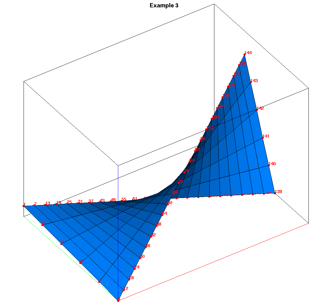
This example shows XZ Twisted, as shown in last image. Create a 6 x 24 quad grid with a twist. The quadxy command enables assignment to the 4 corners such that the surface is not planer.
Input LaGriT command file for 3 examples: ex_quadxy.lgi