SETTETS
Set mesh object element color (itetclr) and create child points at interior interfaces. This command can also be used to set the node color from the element color. Note color values must be an integer number greater than 0.
SYNTAX
settets
settets / color_tets

settets / parents

settets / geometry

settets/ color_points

settets/ new_tets

settets / normal
settets and
settets/color_tets detirmines the color of all elements using the following tests;
If the element contains a non-interface point, the element color is set to this value. If the
element is comprised entirely of interface points, the centroid of the element is calculated and the material region containing this point is determined; the element color is set to this material. If the centroid of the element is not in any material region, the centroid must be on an interface surface. In this case all vertices of the element are examined
and the material common to all vertices is selected as the element color.
settets / parents has exactly the same behavior as settets except that existing values of itetclr are used for elements containing non-interface nodes.
geometry sets the element itetclr based on the material region containing the centroid of the element for all elements; existing values
of itetclr are ignored and overwritten.
color_points sets the node material imt from the element color itetclr; existing values of itetclr are not changed.
settets/newtets has the same behavior as settets except that existing positive values of itetclr are not changed.
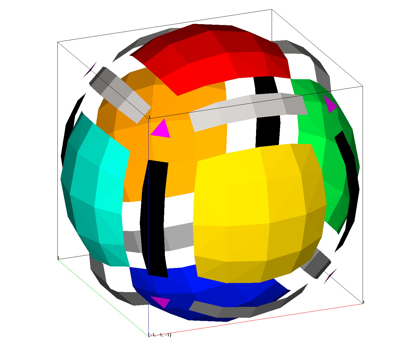
settets/normal assigns the element itetclr array of a triangle mesh to an integer value depending on the normal vector direction. There are 26
possible direction that correspond to the 6 faces, 12 edges and 8
corners of a cube. In general most triangles will be assigned one of 6
values which correspond to the 6 sectors which are within degrees of
the 6 unit vectors: 1 0 0 , 0 1 0 , 0 0 1, -1 0 0, 0 -1 0, 0 0 -1. See image and table below.
NOTE: Valid for a quadrilateral or triangle mesh.
EXAMPLES
# Projected cube onto a sphere to capture all 26 directions

cmo / create / motet_sph
createpts/sphere/1/5/162/1.0,0.5/0.,0.,0./1,0,0.0/
cmo / setatt / motet_sph / imt / 1 0 0 / 1
filter / 1 0 0
rmpoint / compress
connect
cmo / setatt / motet_sph / itetclr / 1 0 0 / 1
resetpts / itp
extract / surfmesh / 1 0 0 / motri_sph / motet_sph
cmo/select/motri_sph

settets/normal
cmo/printatt/motri_sph/ itetclr / minmax
dump / sphere_colors.inp / motri_sph
Creates a sphere shaped triangulated surface with colors 1-26 based on normal directions with the view set so the min x,y,z coordinate is left,front,bottom. Direction numbering starts at bottom then top then right, back, left, front as shown in table and image.
   1   bottom  (blue)
   2   top     (red)
   3   right = east  (green)
   4   back  = north (orange)
   5   left  = west  (aqua)
   6   front = south (yellow)

   7   bottom right edge (dark gray)
   8   bottom front edge (dark gray)
   9   front  right side edge (black)
  10   bottom back edge (dark gray)
  11   back right side edge (black)
  12   bottom left edge (dark gray)
  13   left back side edge (black)
  14   front left side edge (black)

  15   top right edge (light gray)
  16   top front edge (light gray)
  17   top back edge (light gray)
  18   top left edge (light gray)

  19   bottom front right corner (magenta)
  20   bottom back  right corner (magenta)
  21   bottom back  left  corner (magenta)
  22   bottom front left  corner (magenta)

  23   top    front right corner (magenta)
  24   top    back  right corner (magenta)
  25   top    back  left  corner (magenta)
  26   top    front left  corner (magenta)
Image shows triangle elements colored by 26 normal values. Image materials are expanded to show all.
