2. Define Boundaries Using Point Sets
In LaGriT, a pset (or point-set) is a collection of points (nodes) within a mesh object. Similarly, an eltset (element-set) is a collection of mesh elements. By capturing points and elements, discrete manipulations can be performed on them, such as translation, removal, or attribute functions.
In this example, point sets are used to create a boundary on the top surface of the created hex mesh. The boundary will be the intersection of three circles on the top layer of the mesh.
# Set vertices (imt) and cells (itetlcr) to 1
cmo / setatt / mohex / imt / 1 0 0 / 1
cmo / setatt / mohex / itetclr / 1 0 0 / 1

resetpts / itp
Capturing a pset is done through the command
pset / pset_name / select_type / select_type_options
where pset_name is an arbitrary variable name to store the pset into,
select_type is the method of pset selection, and select_type_options are
parameters specific to the chosen select_type for configuring the subset
selection (see the documentation for more information).
2.1 PSet Definitions
As the boundary will live only in the top layer, nodes belonging to the top layer will be identified first.
pset / p_top / attribute / zic / 1 0 0 / ge / Z1
Here, a pset named p_top is created. This pset contains all nodes
(stride = 1 0 0) where the node’s Z value (zic) is greater than or equal to
(ge) the top of the mesh (Z1). Remember that we defined Z1 above for the
initial creation of the mesh - and that by simply changing Z1 and re-running
the script, this pset capture will still be valid for any value of Z1
(where Z1 > Z0).
Now that the top is defined, we will move to defining three cylindrical objects.
This is done through the command
pset / pset_name / geom / rtz / ifirst,ilast,istride / r1,t1,z1 / r2,t2,z2 / xcen,ycen,zcen
which forms a pset of nodes within the cylinder or cylindrical shell given by radius r1 to r2, angle theta t1 to t2 and height z1 to z2.
pset / p_circle1 / geom / rtz / 1 0 0 / 0. 0. -1.0 / &
       1100. 360. 1.e4 / 1500. 1500. 0.
pset / p_circle2 / geom / rtz / 1 0 0 / 0. 0. -1.0 / &
       1100. 360. 1.e4 / 2500. 2500. 0.
pset / p_circle3 / geom / rtz / 1 0 0 / 0. 0. -1.0 / &
       1100. 360. 1.e4 / 2500. 1500. 0.
Above, any points within a full circle (theta = 360) of radius 1100. and
within Z={-1.0,1.e4} are captured. Three different cylinders are created,
where only the centroids change.
Finally, all four psets are intersected such that all points belonging to the
union of all given sets are preserved into the point seet p_region:
pset / p_region / inter / p_top p_circle1 p_circle2 p_circle3
This creates a point-set where all points (i) live on the top layer, and (ii) live within the intersection of the three cylinders.
2.2 Map PSets to an Attribute
As a simple sanity check during meshing, it can be helpful to map mesh operations to an attribute. These can be visualized at intermediate steps in the meshing process to provide a form of verification or debugging.
First, create an attribute using the cmo / addatt command:
cmo / addatt / MONAME / id_top_region / vint / scalar / nnodes
Here, an attribute named id_top_region is created within the mesh MONAME,
and has type integer (vint), is of scalar dimensions, and is a node-based
attribute (nnodes).
The attribute can be progressively filled in with different values based on the psets:
# Fill the entire attribute with 1
cmo / setatt / MONAME / id_top_region / 1 0 0 / 1

# Color all nodes in the pset p_circle1 with the value 2
cmo / setatt / MONAME / id_top_region / pset get p_circle1 / 2

# Color all nodes in the pset p_circle2 with the value 2
cmo / setatt / MONAME / id_top_region / pset get p_circle2 / 3

# And so on...
cmo / setatt / MONAME / id_top_region / pset get p_circle3 / 4
cmo / setatt / MONAME / id_top_region / pset get p_region / 5
Finally, release the psets from memory:
pset / p_top / release
pset / p_circle1 / release
pset / p_circle2 / release
pset / p_circle3 / release
pset / p_region / release
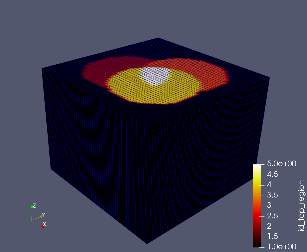
Cutting through the mesh in ParaView, we can visualize id_top_region and
validate that the mesh is being constructed as expected: