3. Constructing Stratigraphy
In the next step of this tutorial, we will build some surfaces to define stratigraphy. In a real model, the surfaces would come from some geologic framework model and would define geologic or hydro-geologic horizons and topography.
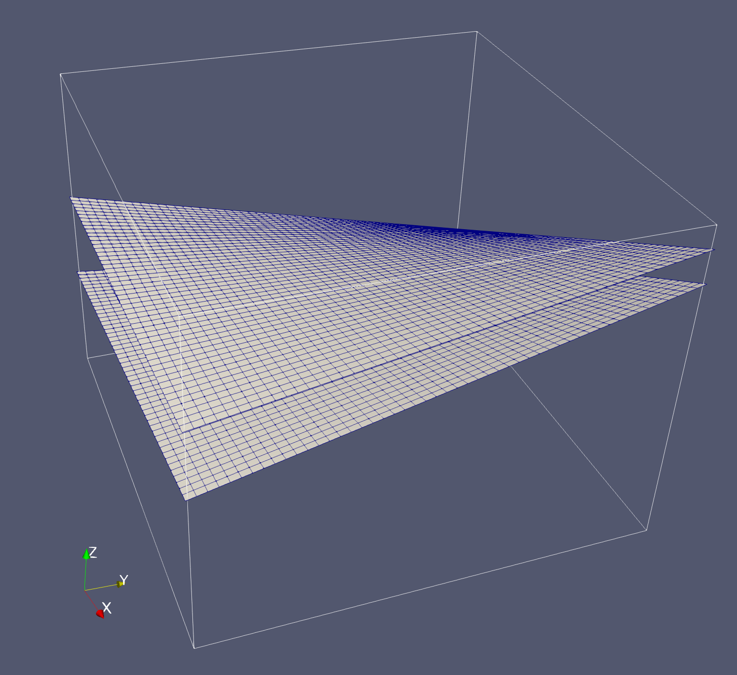
These surfaces will be planar quad meshes that cut through a defined section of the hex mesh. Later, we will map the intersections of the surfaces to the hex mesh.
Create the top surface:
cmo / create / mosurf1
cmo / select / mosurf1

define / X0S /  -20.0
define / X1S / 4020.0
define / Y0S /  -20.0
define / Y1S / 4020.0

define / Z1 / 1000.
define / Z2 / 1500.
define / Z3 / 2500.
define / Z4 /  500.

quadxy / NX NY /X0S Y0S Z1/X1S Y0S Z2/X1S Y1S Z3/X0S Y1S Z4
createpts/brick/xyz/ NX NY 1 /1,0,0/connect
Note that the X and Y domains of the quad mesh exceed that of the hex mesh. This serves two purposes. First, it serves as a helpful visualization aid, allowing one to easily see how the surfaces cut the hex mesh without adjusting opacity. Second, and more importantly, it ensures that all elements cut by the surfaces will be properly recognized as such. Rounding errors may affect elements at the perimeter of the cutting planes from being properly labeled.
Create the bottom surface:
cmo / create / mosurf2
cmo / select / mosurf2

define / Z1 / 1800.
define / Z2 / 2100.
define / Z3 / 2800.
define / Z4 /  800.
quadxy / NX NY /X0S Y0S Z1/X1S Y0S Z2/X1S Y1S Z3/X0S Y1S Z4
createpts/brick/xyz/ NX NY 1 /1,0,0/connect