4. Map Surfaces to Mesh
Now that the straitipgrahy has been modeled and we are comfortable with our results, we will map their spanning domain to the parent mesh. As done with the psets above, this process will be driven via attributes.
We now have two planes spanning the X,Y domain of the mesh. These planes can be leveraged to create different material IDs at different regions of the subsurface.
For example,
- For all nodes/cells above plane 1, set their material ID to 1
- For all nodes/cells between plane 1 and plane 2, set their material ID to 2
- For all nodes/cells below plane 2, set their material ID to 3
This process can be accomplished by:
- Defining the above regions using the
regionkeyword - Capturing the relevant nodes and elements that fall within the defined regions
- Setting the node and element material IDs based on the
psetsandeltsets
4.1 Defining Regions
The syntax for region is:
region / region_name / region_definition
where region_definition is a string composed of boolean operators and
instantiated surface objects.
Recall that we have defined two planes, mosurf1 and mosurf2. We would like
to generate the region objects from these planes, but the arguments for
region require surface objects.
Fortunately, we can map the planes to a surface very easily. The syntax for
generating a surface object from a quad or triangle mesh is:
surface / surface_name / reflect / sheet / input_mesh
The two planes can then be mapped to surface objects:
surface / s_1 / reflect / sheet / mosurf1
surface / s_2 / reflect / sheet / mosurf2
And finally, we can remove the plane meshes and define regions:
cmo / delete / mosurf1
cmo / delete / mosurf2
cmo / select / MONAME

region / r_1 / le s_1
region / r_2 / gt s_1 and le s_2
region / r_3 / gt s_2
4.2 Creating Eltsets and PSets from Regions
Point sets and element sets can easily be created through region objects. The syntax is:
 pset / pset_name / region / region_object / 1,0,0
 eltset / eltset_name / region / region_object
Applying this to our region objects yields:
pset   / p_r_1 / region / r_1 / 1 0 0
pset   / p_r_2 / region / r_2 / 1 0 0
pset   / p_r_3 / region / r_3 / 1 0 0

eltset / e_r_1 / region / r_1
eltset / e_r_2 / region / r_2
eltset / e_r_3 / region / r_3
4.3 Setting Attributes from Eltsets and PSets
Recall that the node attribute imt holds the ‘node colors’ of the mesh, and
cell attribute itetclr stores the ‘cell colors’ (or material ID).
Let’s use the defined psets and eltsets to change these:
cmo / setatt / MONAME / imt     / pset   get p_r_1 / 1
cmo / setatt / MONAME / imt     / pset   get p_r_2 / 2
cmo / setatt / MONAME / imt     / pset   get p_r_3 / 3

cmo / setatt / MONAME / itetclr / eltset get e_r_1 / 1
cmo / setatt / MONAME / itetclr / eltset get e_r_2 / 2
cmo / setatt / MONAME / itetclr / eltset get e_r_3 / 3
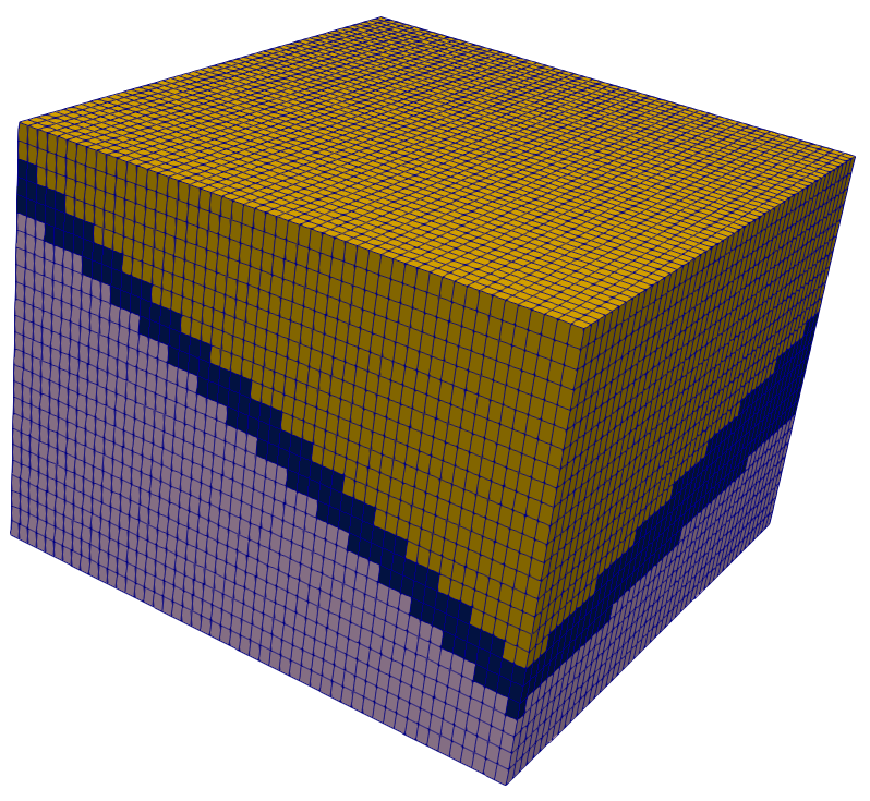
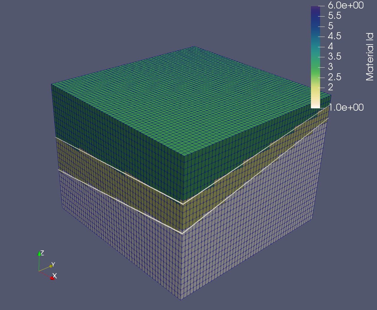
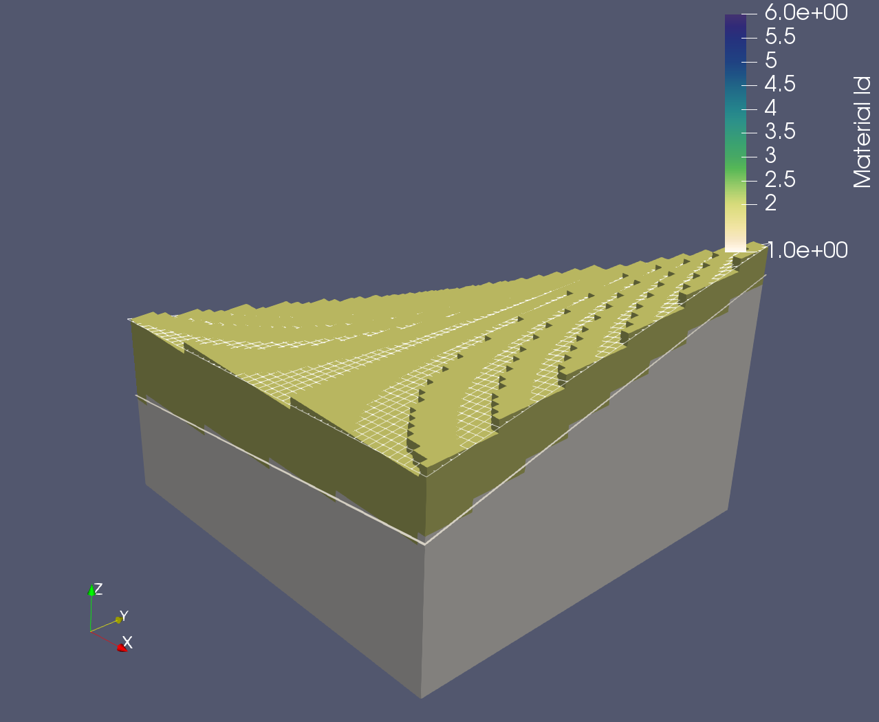
Our mesh’s cells and nodes now store information about their intersections
with the cut-planes. Visualizing itetclr, we can see that this has behaved
as expected: