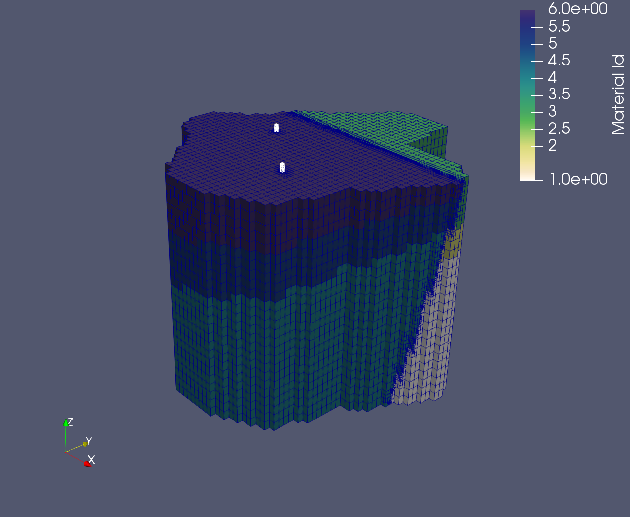
8. Insert Wells
In this step, we will generate two cylindrical ‘wells’, refine the mesh
MONAME around them, and identify a line of nodes that will be the well
source/sink for boundary conditions (ultimately writing these nodes
to zone files).
8.1 Generating Cylindrical Tetrahedral Wells
First, we define variables for the well’s position (XWELL,YWELL), radius (RADIUS_WELL), and number of nodes across the cylindrical radius
(NRADIUS):
define / XWELL1 / 1234.56
define / YWELL1 / 1987.65

define / XWELL2 / 2243.21
define / YWELL2 / 1212.34

define / RADIUS_WELL / 25.0
define / NRADIUS / 2
Now, we create a cylindrical point cloud defining the first well using
createpts / rtz:
cmo / create / mo_well1 / / / tet
createpts / rtz / NRADIUS 9 NZ / 0. 0. 3100. / RADIUS_WELL 360. 1500. / 1 1 1
This creates a point cloud centered around (0,0,0) with a radius of RADIUS_WELL, an angular component spanning a full 360 degrees (φ = {0., 360.}), and a Z range of {3100.,1500.}.
Run filter, rmpoint / compress, and set imt to 1 for the well:
filter / 1 0 0
rmpoint / compress
cmo / setatt / mo_well1 / imt / 1 0 0 / 1
Next, connect the point cloud into a tetrahedral mesh and translate the
X and Y origin to {XWELL1,YWELL1}:
connect
resetpts / itp
cmo / printatt / mo_well1 / -xyz- / minmax
trans / 1 0 0 / 0. 0. 0. / XWELL1 YWELL1 0.0
cmo / printatt / mo_well1 / -xyz- / minmax
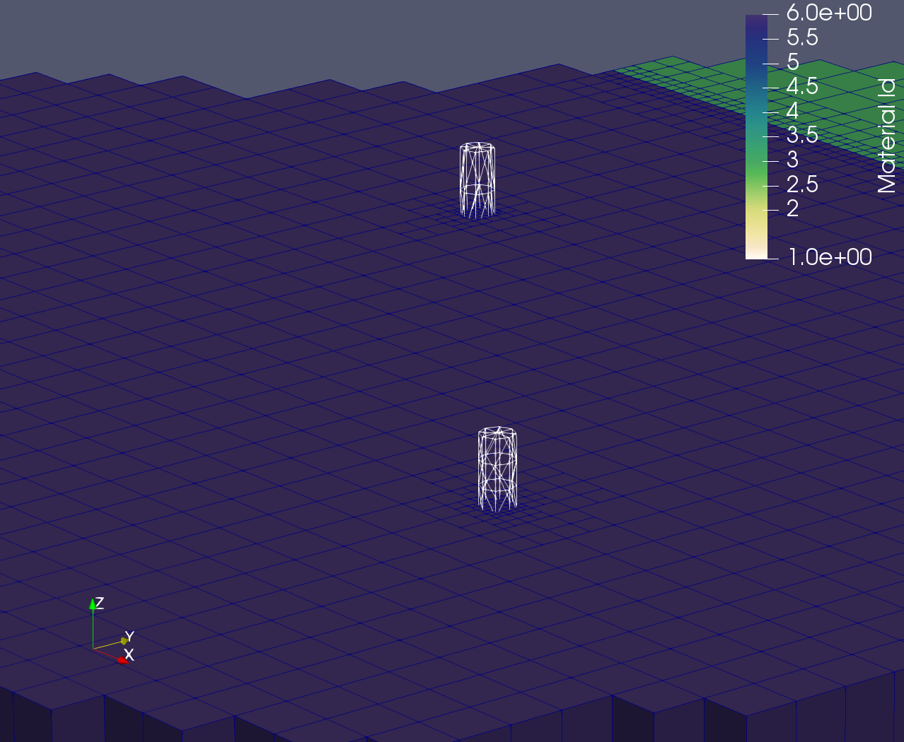
The first ‘well’ mesh object has been generated. Repeat this process with different parameters to create the second well:
cmo / create / mo_well2 / / / tet
createpts / rtz / NRADIUS 9 NZ / 0. 0. 3100. / RADIUS_WELL 360. 2200. / 1 1 1
filter / 1 0 0
rmpoint / compress
cmo / setatt / mo_well1 / imt / 1 0 0 / 1
connect
resetpts / itp
cmo / printatt / mo_well2 / -xyz- / minmax
trans / 1 0 0 / 0. 0. 0. / XWELL2 YWELL2 0.0
cmo / printatt / mo_well2 / -xyz- / minmax
Finally, join the two distinct wells into a single mesh object with addmesh / merge:
addmesh / merge / mo_wells / mo_well1 mo_well2
8.2 Refining MONAME around the wells
As we did for the fault in step 7, we refine the main mesh MONAME around the wells:
# First pass refinement
cmo / select / MONAME
intersect_elements / MONAME / mo_wells / if_inter
eltset / e_refine / if_inter / gt / 0
refine/ eltset / eltset get e_refine
cmo / setatt / MONAME / if_inter / 1 0 0 / 0
eltset / e_refine / delete

# Second pass refinement
cmo / select / MONAME
intersect_elements / MONAME / mo_wells / if_inter
eltset / e_refine / if_inter / gt / 0
refine/ eltset / eltset get e_refine
cmo / setatt / MONAME / if_inter / 1 0 0 / 0
eltset / e_refine / delete

# Third pass refinement
cmo / select / MONAME
intersect_elements / MONAME / mo_wells / if_inter
eltset / e_refine / if_inter / gt / 0
refine/ eltset / eltset get e_refine
cmo / setatt / MONAME / if_inter / 1 0 0 / 0
eltset / e_refine / delete
The refinement process returns a octree grid object, which stores information about parent-children relationships, among other properties. It’s important, as the prepare to finalize the mesh for exporting, to strip this information and convert the octree grid object to a standard mesh object.
This conversion is done through the grid2grid / tree_to_fe command:
grid2grid / tree_to_fe / mohex_octree /  mohex
define / MONAME / mohex_octree
8.3 Writing zone files based on well distances
The zone files are lists of node numbers in FEHM file format and used to identify materials, well source/sinks, and boundary conditions.
In this subsection, we will generate zone files describing all nodes within 32, 16, 8, 4, 2 and 1 meters of the wells.
To begin, we will compute the well point cloud again, as we did above. First, for well 1:
cmo / create / mo_pts1
createpts / rtz / 2 2 1000 / 0. 0. 3100. / 0.0 360. 2200. / 1 1 1
trans / 1 0 0 / 0. 0. 0. / XWELL1 YWELL1 0.0
Then for well 2:
cmo / create / mo_pts2
createpts / rtz / 2 2 1000 / 0. 0. 3100. / 0.0 360. 2200. / 1 1 1
trans / 1 0 0 / 0. 0. 0. / XWELL2 YWELL2 0.0
and joining them into a single mesh object, mo_pts:
addmesh / merge / mo_pts / mo_pts1 / mo_pts2
cmo / select / mo_pts
filter / 1 0 0
rmpoint / compress
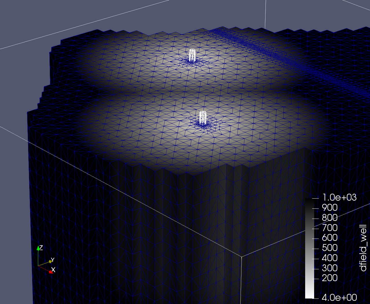
Next, we will compute a distance field attribute, dfield_well, which is a node-based attribute storing the Euclidean distance from node_i in one mesh to the closest node in another mesh. In other words, all nodes in MONAME store their distance to the closest well (mo_pts) node.
compute / distance_field / MONAME / mo_pts / dfield_well
Clean up unneeded mesh objects:
cmo / delete / mo_pts1
cmo / delete / mo_pts2
cmo / delete / mo_pts
cmo / delete / mo_wells
cmo / delete / mo_well1
cmo / delete / mo_well2
And finally, for each mesh-to-well distance in {32,16,8,4,2,1} (which is stored in dfield_well), (i) create a pset object
containing all nodes within that distance, and (ii) write those nodes to a zone file:
cmo / select / MONAME

pset / pwell / attribute / dfield_well / 1 0 0 / le / 1.0
pset / pwell / zone / zone_radius_01.0.zone

pset / pwell / attribute / dfield_well / 1 0 0 / le / 2.0
pset / pwell / zone / zone_radius_02.0.zone

pset / pwell / attribute / dfield_well / 1 0 0 / le / 4.0
pset / pwell / zone / zone_radius_04.0.zone

pset / pwell / attribute / dfield_well / 1 0 0 / le / 8.0
pset / pwell / zone / zone_radius_08.0.zone

pset / pwell / attribute / dfield_well / 1 0 0 / le / 16.0
pset / pwell / zone / zone_radius_16.0.zone

pset / pwell / attribute / dfield_well / 1 0 0 / le / 32.0
pset / pwell / zone / zone_radius_32.0.zone