Regions and Points to Tetrahedral Mesh
Generating Initial Grids Using the LaGriT Command Language
The steps involved in generating three dimensional grids in the LaGriT command language are:
- Define mesh objects.
- Define an enclosing volume.
- Define interior interfaces.
- Divide the enclosing volume into regions.
- Assign material types to the regions.
- Distribute points within the volume.
- Connect the points into tetrahedra
Detailed descriptions of the LaGriT commands are given in Section II. This tutorial covers just the commands needed to generate a simple grid. The tutorial will explain how to generate a grid in a unit cube containing two materials separated by a plane. Lines that begin with an asterisk (*) are comments; keywords are in bold.
1. Define mesh objects
Define all Mesh Objects to be used in this problem using the cmo/create command. The cmo/create command establishes an
empty Mesh Object data structure (see Section III.a for a description).
For this example we will need only a single 3D Mesh Object:
Create a 3D tetrahedral mesh object and name it 3dmesh:
cmo/create/3dmesh/
2. Define an enclosing volume
Define an enclosing volume using the surface
command. Since we are defining an exterior boundary, the boundary type
is reflect. The next item of information needed is the geometry of
the volume; some common geometry types are box, cylinder,
and sphere. Geometry types box and sphere define closed
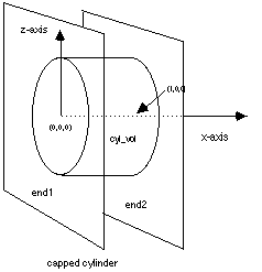
volumes; whereas a cylinder is open on both ends and must be capped
by planes.
Along with the geometry type, the extent of the volume is defined by specifying for the box its corners, or for the cylinder its radius and end point of its axis of rotation. The enclosing volume must be convex. Complicated enclosing volumes can be described by their bounding surfaces including planes and sheets.
Some simple examples of enclosing volumes are:
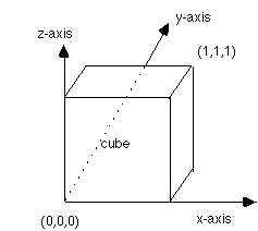
Unit cube:
surface/cube/reflect/box/0.0,0.0,0.0/1.0,1.0,1.0
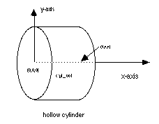
Cylinder whose axis is the x axis with radius 1 and height 1:
surface/cyl_vol/reflect/cylinder/0.,0.,0./1.,0.,0./1.
surface/end1/reflect/plane/0.,0.,0./0.,0.,1./0.,1.,1.
surface/end2/reflect/plane/1.,0.,0./1.,0.,1./1.,1.,1.
3. Define interior interfaces
Interfaces are defined with the surface
command. In this case the boundary type is intrface. If the command
defines a volume (e.g. box, cylinder) then the interface is the surface
of the volume defined. If the command defines a plane or sheet then the
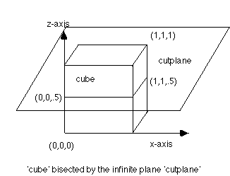
interface is the plane or sheet. It is important to remember that planes
are infinite and that the order of points specifying the plane
determines a normal to the plane in the usual right-hand-rule sense
(see Section II.a.9). This direction is important in
determining regions. In order to divide the unit cube defined above in
half vertically, define a plane by:
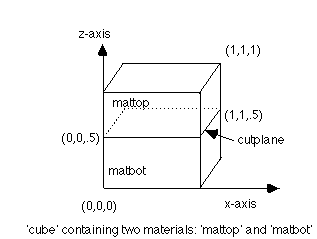
surface/cutplane/intrface/plane/0.,0.,.5/1.,0.,.5/1.,1.,.5
The normal to this plane points in the positive z direction.
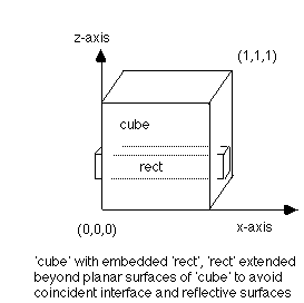
Interfaces must not be coincident with reflective boundaries. For example to embed a rectangle inside a cube, it is necessary to extend the ends of the rectangle beyond the cube to avoid coincident reflective and interface surfaces:
surface/cube/reflect/box/0.0,0.0,0.0/1.0,1.0,1.0
surface/rect/intrface/box/-0.1,0.5,0.2/1.1,0.6,0.5
4. Divide the enclosing volumes into regions
The region command is used to divide the
enclosing volume into regions. The directional operators lt, le,
gt, and ge are applied to previously defined surfaces
according to the following rules.
-
lt– if the surface following is a volume thenltmeans inside not including the surface of the volume. If the surface is a plane or a sheetltmeans the space on the side of the plane or sheet opposite to the normal not including the plane or sheet itself. -
le– if the surface following is a volume thenlemeans inside including the surface of the volume. If the surface is a plane or a sheetlemeans the space on the side of the plane or sheet opposite to the normal including the plane or sheet itself. -
gt– if the surface following is a volume thengtmeans outside not including the surface of the volume. If the surface is a plane or a sheet gt means the space on the same side of the plane or sheet as the normal not including the plane or sheet itself. -
ge– if the surface following is a volume thengemeans outside including the surface of the volume. If the surface is a plane or a sheetgemeans the space on the same side of the plane or sheet as the normal including the plane or sheet itself.
In region comands, surface names must be preceeded by a directional
operator. The logical operators or, and, and not mean union,
intersection and complement respectively. Parentheses are operators and
are used for nesting. Spaces are required as delimiters to separate
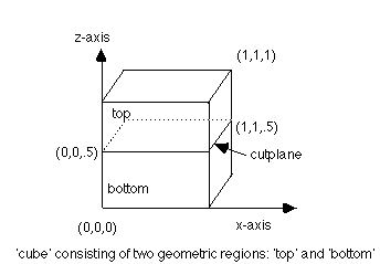
operators and operands. To define the two regions created by the plane
bisecting the unit cube:
region/top/ le cube and gt cutplane
region/bottom/ le cube and le cutplane
The region bottom contains the interface cutplane; top contains none
of the interface. Interior interfaces must be included in one and only
one region.
If a region touches an external boundary, include the surface that
defines the enclosing volume in region and mregion commands. For
example, the regions top and bottom are enclosed by the surface
cube
5. Assign material types to the regions
Assign materials to regions using
the mregion command. This command has
similar syntax to the region command except
that the interface should not be assigned to any material region. To
assign two materials, mattop and matbot, to the regions top and
bottom:
mregion/ mattop/ le cube and gt cutplane /
mregion/ matbot/ le cube and lt cutplane /
6. Distribute points within the volume
There are many methods of distributing points within a volume. For
simple geometries refer to the createpts command.
This example uses the regnpts command which, although more complicated,
provides greate flexibility. Points are distributed within regions
using Cartesian, cylindrical or spherical coordinates by constructing
rays that travel through regions and distributing points along these
rays. For this example, points are distributed using Cartesian
coordinates. The rays are specified by defining a set of points and a
plane. For each point in the set, a ray is constructed normal to the
plane passing through the point. In general rays are constructed in
sets, each set is specified by a single plane and a set of points. The
createpts command is used to create the points. The
regnpts command is used to specify the plane, to specify
the region, and to specify the number of points to be distributed along
the rays.
The points and the plane should lie outside the enclosing volume and on opposite sides. The normal to the plane should point toward the point. As rays are created, if they do not pass through the specified region, no points are distributed. Points may be spaced evenly along the ray or they may be spaced according to a ratio.
The following commands will place points in the unit cube.
# create 25 points (5x5x1) in a plane above the unit cube
# place points on the boundaries in the x and y directions (1,1,0)
createpts/xyz/5,5,1/0.,0.,1.1/1.,1.,1.1/1,1,0/

# give the points defined by the createpts command the name, rayend
pset/rayend/seq/1,0,0/
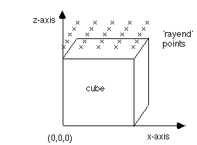
# create rays between points in rayend and the plane below the cube
# distribute 3 points along these rays in the region top
# add one point at the upper external boundary for each ray
regnpts/top/3/pset,get,rayend/xyz/0.,0.,-.1/0.,1.,-.1/1.,1.,-.1/0,0/
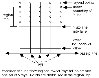
# distribute 4 points along these rays in the region *bottom*
# add one point at the lower external boundary for each ray
# add one point at the material interface for each ray since
# *bottom* contains the interface - a total of 5 points for each ray.
# points will be distributed such that the ratio of distances between
# any two consecutive pairs of points is 0.6 traveling from the source
# of the ray (the plane) to the ray end.

regnpts/bottom/4/pset,get,rayend/xyz/0.,0.,-.1/0.,1.,-.1/1.,1.,-.1/1,.6/
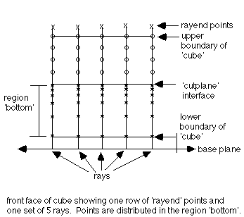
Other versions of the regnpts are appropriate for cylindrical and
spherical geometries. For cylindrical geometries the createpts
command specifies points in a cylindrical shell outside the volume.
The regnpts command specifies a line (usually the cylinder axis), and
the rays are constructed normal to this line and containing one of the
createpts points. For spherical geometries the createpts command
specifies points in a spherical shell outside the volume. The regnpts
command specifies a point (usually the center of the sphere)
from which rays are constructed to the createpts points.
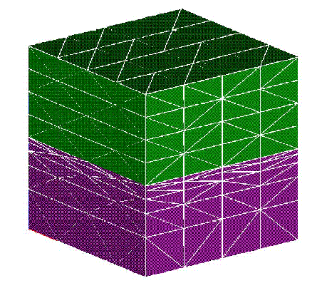
7. Connect the points into tetrahedra
The mesh designer may use the following set of command to connect the points into a tetrahedral mesh:
# eliminate coincident or nearly coincident points
# 1,0,0 means consider all points
filter/1,0,0/

# rayend points are set to invisible (21 is the code for invisible)
# they were used as end points of the rays in the regnpts command
cmo/setatt//itp/pset,get,rayend/21/

# assign material colors to the points
# identify points that are on material interfaces
# identify constrained points
setpts

# connect the points into a Delaunay tetrahedral mesh
# do not connect across material interfaces -
# add points if necessary to resolve material interfaces
connect

# set element (tetrahedral) type
settets

# dump mesh to some output form
dump/gmv/filename

# terminate processing
finish
Full Tutorial Code:
# create a 3D tetrahedral mesh object and name it *3dmesh*
cmo/create/3dmesh/

# unit cube
surface/cube/reflect/box/0.0,0.0,0.0/1.0,1.0,1.0/

# define z=.5 plane as interface
surface/cutplane/intrface/plane/0.,0.,.5/1.,0.,.5/1.,1.,.5/

# define geometric regions
region/top/ le cube and gt cutplane/
region/bottom/ le cube and le cutplane /

# define material regions
mregion/mattop/ le cube and gt cutplane /
mregion/matbot/ le cube and lt cutplane /

# create 25 points (5x5x1) in a plane above the unit cube
# place points on the boundaries in the x and y directions (1,1,0)
createpts/xyz/5,5,1/0.,0.,1.1/1.,1.,1.1/1,1,0/

# give the points defined by the createpts command the name, rayend
pset/rayend/seq/1,0,0/

# create rays between points in rayend and the plane below the cube
# distribute 3 points along these rays in the region top
# add one point at the upper external boundary for each ray
regnpts/top/3/pset,get,rayend/xyz/0.,0.,-.1/0.,1.,-.1/1.,1.,-.1/0,0/

# distribute 4 points along these rays in the region *bottom*
# add one point at the lower external boundary for each ray
# add one point at the material interface for each ray since
# *bottom* contains the interface - a total of 5 points for each ray.
# points will be distributed such that the ratio of distances between
# any two consecutive pairs of points is 0.6 traveling from the source
# of the ray (the plane) to the ray end.

regnpts/bottom/4/pset,get,rayend/xyz/0.,0.,-.1/0.,1.,-.1/1.,1.,-.1/1,.6/

# eliminate coincident or nearly coincident points
# 1,0,0 means consider all points
filter/1,0,0/

# rayend points are set to invisible (21 is the code for invisible)
# they were used as end points of the rays in the regnpts command
cmo/setall//itp/pset,get,rayend/21/

# assign material colors to the points
# identify points that are on material interfaces
# identify constrained points
setpts

# connect the points into a Delaunay tetrahedral mesh
# do not connect across material interfaces -
# add points if necessary to resolve material interfaces
connect

# set element (tetrahedral) type
settets

# dump mesh to some output form
dump/gmv/filename

# terminate processing
finish
