Step 2. Create Tet Mesh from the Hex Mesh
LaGriT command file: 02_hex_to_tet.lgi
LaGriT output file: lagrit.out
LaGriT all run files: Folder step_02
This example will use 2 methods for creating a tet mesh from a hex mesh.
- Method 1 will use the mesh points to ‘connect’ into a Delaunay tet mesh.
- Method 2 will use ‘grid2grid’ to convert hex elements into tetrahedrals.
Use of hextotet (or grid2grid) to convert a 3D mesh to a tetrahedral mesh may result in a non-Delaunay tetrahedral mesh. If the target simulator is one that uses two-point flux approximation and Voronoi control volumes (FEHM, PFLOTRAN, TOUGH2) then the connect command should be used to create a Delaunay mesh.
Click here for Delaunay Definition
Click here for Voronoi Definition
Click here for more details on the connect algorithm
Method 1 using Connect Delaunay
The Delaunay algorithm is applied to a set of points. In this example we will use the nodes from the hex mesh in Step 1. The point distribution will impact the success of a connected tet mesh. A point distribution where spacing varies from very small to very large can result in high aspect ratios and boundary problems. This hex mesh provides structured regular spacing and is topologically consistent and will result in a successful Delaunay connection.
Create the Hex Mesh from Step 1
The ‘infile’ command is used to read and run a LaGriT command file. In this case we read and run the same command file that was used to create a hex mesh in Step 1. Use the ‘cmo/status’ commands to confirm the mesh object named “3dmesh” was created.
infile 01_create_hex.lgi
cmo/status/ 3dmesh / brief
The status report should indicate the current mesh object is a hex mesh with 1122 nodes and 800 hex elements.
The current-mesh-object(CMO) is: 3dmesh

  1 Mesh Object name: 3dmesh
    number of nodes =          1122        number of elements =          800
    dimensions geometry =         3        element type =                hex
    dimensions topology =         3        8 nodes      6 faces     12 edges
    boundary flag =        16000000        status =                   active
Create a new mesh object with points to connect
The ‘connect’ command will create connectivity from a cloud of points. There should be no duplicate points, and the imt material should be a single value.
Copy the hex points into a new mesh object, this removed the connectivity so new elements can be created.
cmo / create / mo_tet
copypts / mo_tet / 3dmesh
We now have multiple mesh objects that can be listed. Use cmo/select command to make “mo_tet” mesh object current for the next commands. Note the cmo/status command shows there are no elements in this mesh object. The “brief” option will show the mesh object summary without the long list of associated attributes.
cmo / list
cmo/ select / mo_tet
cmo/ status / mo_tet / brief
The current-mesh-object(CMO) is: mo_tet

  0    Mesh Object name: -default-
  1    Mesh Object name: 3dmesh
  2    Mesh Object name: mo_tet
cmo/select/mo_tet
cmo/status/mo_tet/brief

The current-mesh-object(CMO) is: mo_tet

  2 Mesh Object name: mo_tet
    number of nodes =          1122        number of elements =            0
    dimensions geometry =         3        element type =                tet
    dimensions topology =         3        4 nodes      4 faces      6 edges
    boundary flag =        16000000        status =                   active
Prepare the points by removing duplicates and setting imt to a single value and boundary tags to 0. The filter command will mark duplicate points as “dudded” points; the rmpoint/compress command will remove the dudded nodes from the mesh object. These commands will not make any changes if there are no duplicate points.
Note: the special token “;” can be used to call multiple commands on the same line.
# Remove duplicate points if they exist
filter/1,0,0 ; rmpoint/compress

# Set some defaults for the connect routine
cmo / setatt / mo_tet / imt / 1 0 0 / 1
cmo / setatt / mo_tet / itp / 1 0 0 / 0

# Create Delaunay tet connectivity of all nodes in the mesh
connect
The result of the connect command should show success.
 Coordinates of enclosing tetrahedron are:
          -0.20000D+03   -0.37500D+02   -0.60000D+02
           0.50000D+02   -0.37500D+02    0.34000D+03
           0.30000D+03   -0.37500D+02   -0.60000D+02
           0.50000D+02    0.21250D+03    0.40000D+02

 Successfully eliminated all multimaterial connections.

 The mesh is now complete!
It is good practice to check the results to make sure there are no zero or negative volume elements with the quality command.
quality
epsilonl, epsilonaspect:   3.0526086E-11  2.8445488E-32
--------------------------------------------
elements with aspect ratio < .01:                    0
elements with aspect ratio b/w .01 and .02:          0
elements with aspect ratio b/w .02 and .05:          0
elements with aspect ratio b/w .05 and .1 :          0
elements with aspect ratio b/w .1  and .2 :          0
elements with aspect ratio b/w .2  and .5 :        926
elements with aspect ratio b/w .5  and 1. :       3874
min aspect ratio =  0.4483E+00  max aspect ratio =  0.6202E+00

epsilonvol:   8.8817842E-08
---------------------------------------
All elements have volume 8.3333333E+01
-----------------------------------------------------------
      4800 total elements evaluated.
Set the tet materials to 1 and update the itp array.
cmo / setatt / mo_tet / itetclr / 1
resetpts / itp
Method 2 converts each hex into 5 tets
The ‘grid2grid’ is a wrapper that simplifies many of the grid-to-grid conversions. In this case we will use the option that converts each hex element into 5 tets (with no points added). This command requires the creation of a new mesh object, the new name is given first, with the source mesh object name at the end.
grid2grid / hextotet5 / mo_hex2tet / 3dmesh
Check the list of mesh objects, the new “mo_hex2tet” mesh object should now be current as the newly created object. Check for positive volumes and set mesh default values.
cmo / list
quality
cmo / setatt / mo_hex2tet / itetclr / 1
resetpts / itp
There are now 3 mesh objects. “3dmesh” is the hex mesh created at start of this run. “mo_tet” was created with the connect command. “mo_hex2tet” was created by the grid2grid/hextotet5 command. Note the quality command is evaluating the current mesh object, “cmo_hex2tet”.
The current-mesh-object(CMO) is: mo_hex2tet

  0    Mesh Object name: -default-
  1    Mesh Object name: 3dmesh
  2    Mesh Object name: mo_tet
  3    Mesh Object name: mo_hex2tet

quality

epsilonl, epsilonaspect:   3.0526086E-11  2.8445488E-32
--------------------------------------------
elements with aspect ratio < .01:                    0
elements with aspect ratio b/w .01 and .02:          0
elements with aspect ratio b/w .02 and .05:          0
elements with aspect ratio b/w .05 and .1 :          0
elements with aspect ratio b/w .1  and .2 :          0
elements with aspect ratio b/w .2  and .5 :          0
elements with aspect ratio b/w .5  and 1. :       4000
min aspect ratio =  0.6202E+00  max aspect ratio =  0.8165E+00

epsilonvol:   8.8817842E-08
---------------------------------------
element volumes b/w 0.8333E+02 and 0.9572E+02:      3200
element volumes b/w 0.9572E+02 and 0.1100E+03:         0
element volumes b/w 0.1100E+03 and 0.1263E+03:         0
element volumes b/w 0.1263E+03 and 0.1451E+03:         0
element volumes b/w 0.1451E+03 and 0.1667E+03:       800
min volume =   8.3333333E+01 max volume =   1.6666667E+02
-----------------------------------------------------------
      4000 total elements evaluated.
Now we have two tet meshes, one created with connect and the other with grid2grid. In general, we use the connect algorithm to create Delaunay meshes using Voronoi control volumes (FEHM, PFLOTRAN, TOUGH2). Converting hex elements into tet elements will not be Delaunay and may affect results depending on the physics used.
For viewing these new meshes, we can add node and element attributes. With the following commands we add values for each tet volume and for the voronoi volume around each mesh node.
See a list of attributes that can be created at cmo/addatt
cmo/addatt / mo_tet / volume / tet_vol
cmo/addatt / mo_tet / voronoi_volume / vor_vol

cmo/addatt / mo_hex2tet / volume / tet_vol
cmo/addatt / mo_hex2tet / voronoi_volume / vor_vol

cmo/printatt/ mo_tet / tet_vol / minmax
cmo/printatt/ mo_tet / vor_vol / minmax
cmo/printatt/ mo_hex2tet / tet_vol / minmax
cmo/printatt/ mo_hex2tet / vor_vol / minmax

dump/avs/02_tet_connect.inp/mo_tet
dump/avs/02_hex2tet5.inp/mo_hex2tet
We can use the cmo/printatt command to view the minmax values of the attributes in named mesh objects.
cmo/printatt/ mo_tet / tet_vol / minmax
cmo/printatt/ mo_tet / vor_vol / minmax
cmo/printatt/ mo_hex2tet / tet_vol / minmax
cmo/printatt/ mo_hex2tet / vor_vol / minmax
The connect mesh and the hextotet mesh have the same 1122 number of nodes. But the connectivity created 4800 tet elements with connect and 4000 for hextotet mesh. Notice the tet element minmax volumes have different results, the connected mesh has volumes all equal. For this structured point distribution, the voronoi volumes for each node have the same min max range.
cmo/printatt/mo_tet/tet_vol/minmax
ATTRIBUTE NAME              MIN               MAX         DIFFERENCE    LENGTH
 tet_vol            8.333333333E+01  8.333333333E+01 0.000000000E+00      4800

cmo/printatt/mo_tet/vor_vol/minmax
ATTRIBUTE NAME              MIN               MAX         DIFFERENCE    LENGTH
 vor_vol            6.250000000E+01  5.000000000E+02 4.375000000E+02      1122

cmo/printatt/mo_hex2tet/tet_vol/minmax
ATTRIBUTE NAME              MIN               MAX         DIFFERENCE    LENGTH
 tet_vol            8.333333333E+01  1.666666667E+02 8.333333333E+01      4000

cmo/printatt/mo_hex2tet/vor_vol/minmax
ATTRIBUTE NAME              MIN               MAX         DIFFERENCE    LENGTH
 vor_vol            6.250000000E+01  5.000000000E+02 4.375000000E+02      1122
Viewing the Tet Meshes
The following images were created by using Paraview reading the AVS mesh files. Click to see full resolution images.
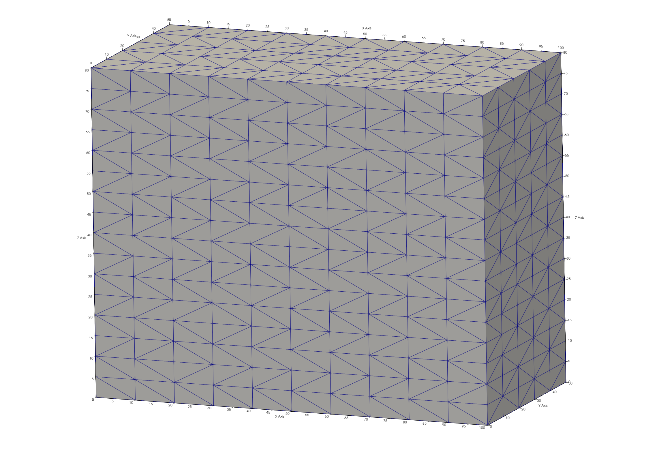
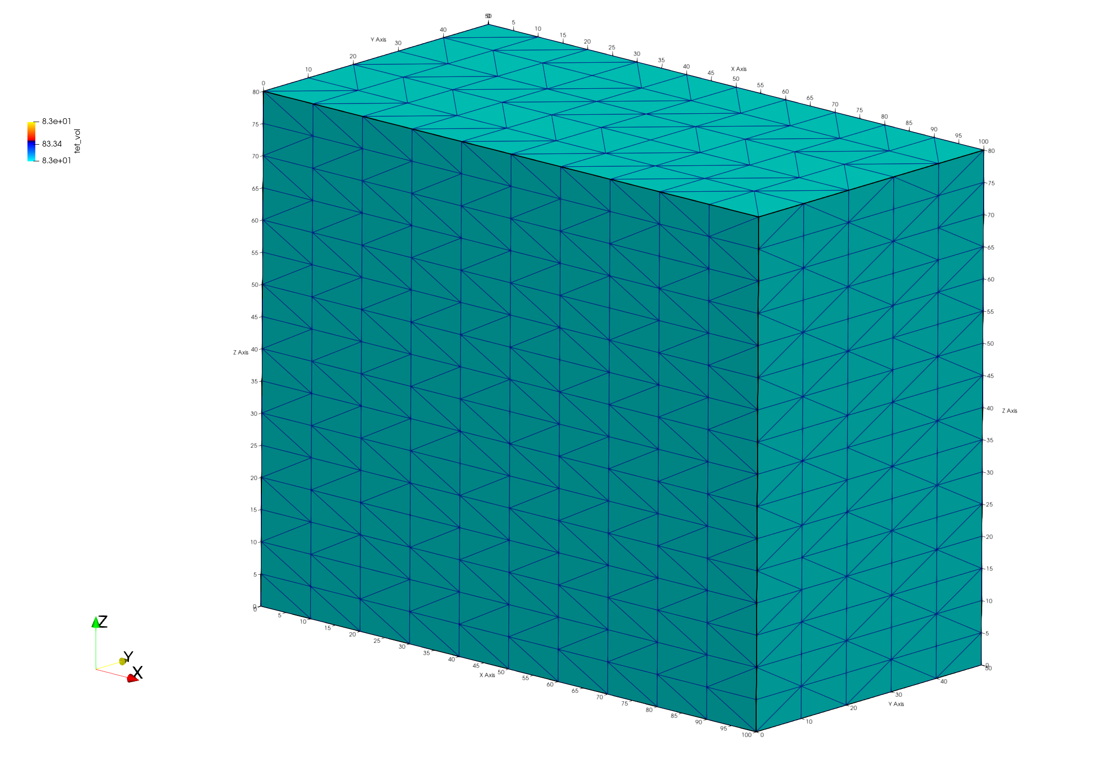
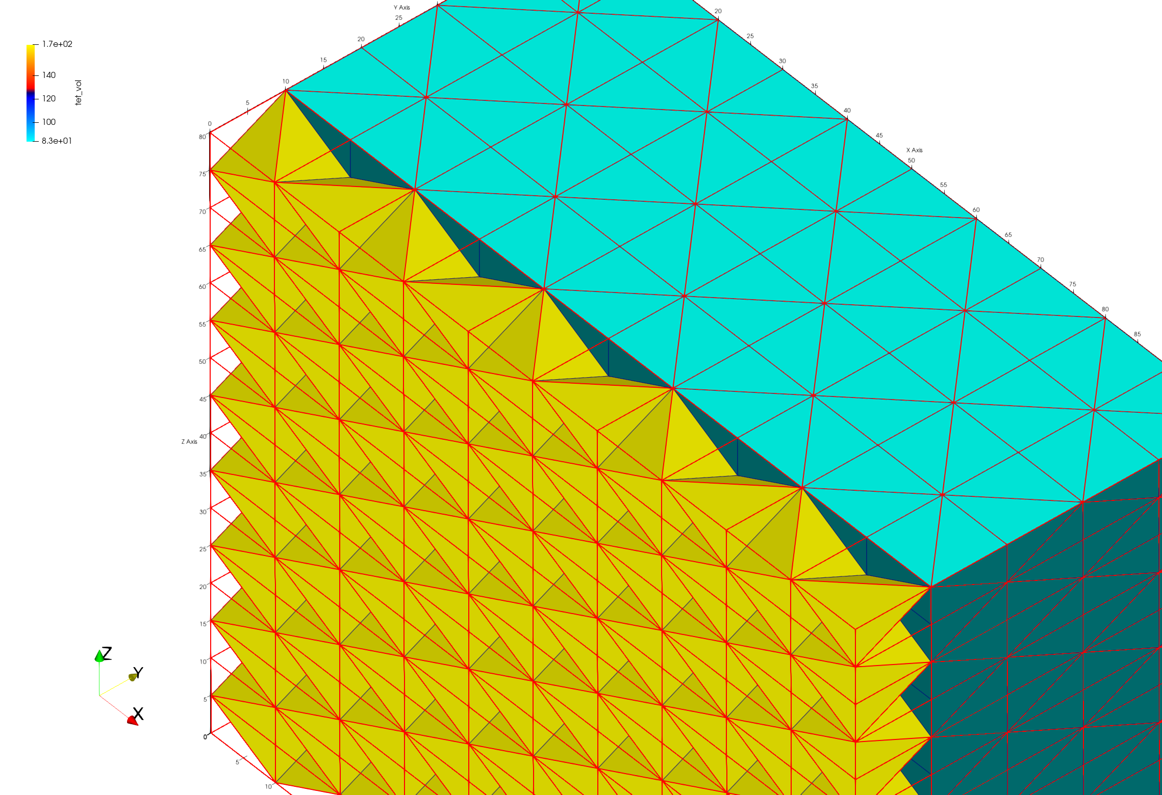
Paraview images show tet elements colored by element volumes of connected Delaunay mesh (left) and grid2grid (right). The grid2grid view is clipped to see the internal tet elements that are larger than the tets formed at the hex corners.
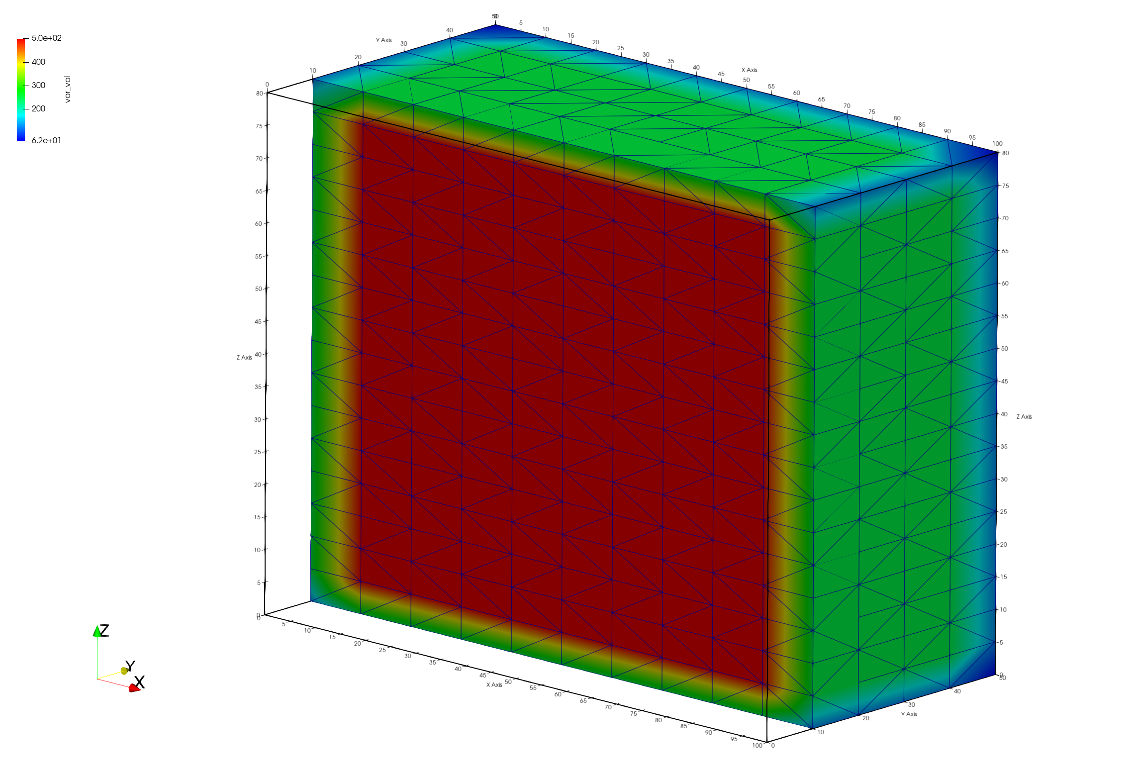
Paraview images show the mesh colored by node voronoi volumes. The boundary nodes will have half volumes, the corner nodes will have quarter volumes. Internal voronoi volumes are all the same. Image is clipped to show internal mesh nodes. Both meshes have the same voronoi volumes.

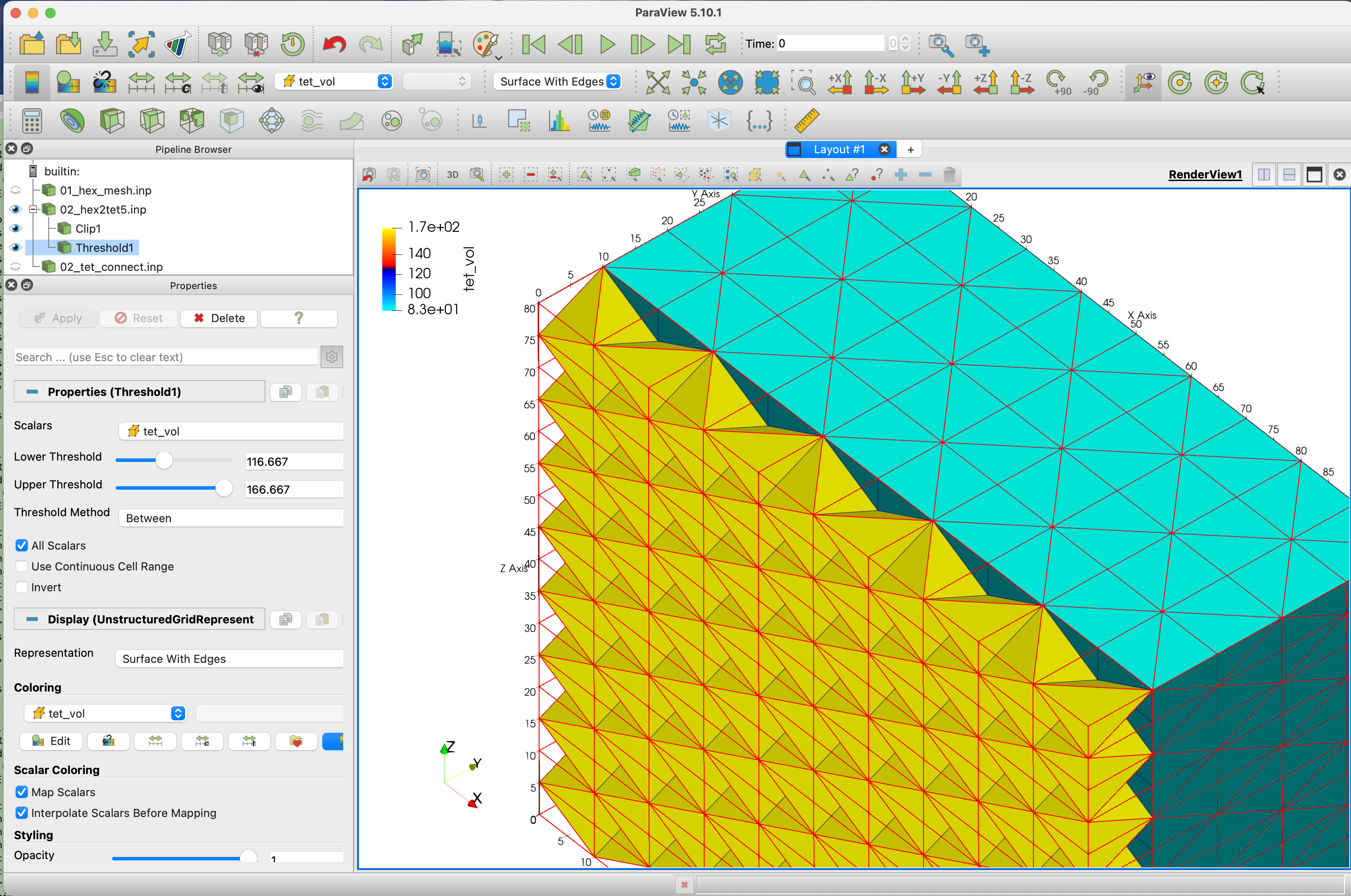
This is a snapshot showing the Paraview settings for the clipped mesh. The full 02_hex2tet5.inp mesh displayed with red wire frame. The mesh is clipped -10, and threshold is used to display tet volumes over 116.
finish
Always end a session or a file with the finish command and a line return after the finish command. The command line parser will not parse a command without a line return.
finish