Step 1. Build a Hex Mesh
LaGriT command file: 01_create_hex.lgi
LaGriT output file: lagrit.out
LaGriT all run files: Folder step_01
Create a Mesh Object
A mesh object can be created by reading a mesh, ie read/avs/mesh.inp/ 3dmesh
or the mesh can be created. For this example, we will start with one of the createpts commands. These are used to add points to a mesh object with defined distributions.
For your first command you will create a 3D mesh object and name it 3dmesh. This will be a structured hex mesh, so we add the element type to the end of the command syntax.
See more on the Mesh Object data structure at LaGriT Mesh Object
Note on spacing: the slashes separate keywords. The slashes with empty spaces are place holders if the user wants to define npoints or nelements in the command. We do not define these here since these values will be updated in the mesh object as points are created.
cmo / create / 3dmesh / / / hex
View the contents of this empty mesh object. Note the mesh attributes nnodes and nelements is currently 0. LaGriT book-keeping routines will update the mesh object as it is modified.
cmo/status/3dmesh
Note: the command cmo/select/3dmesh can be added here, but not necessary because there is only one mesh. Also, the create command makes the created mesh the current mesh.
Create Points for Hex Mesh
We will use one of the simple createpts commands, this version will create a structured rectangular mesh. Checking the syntax for createpts/brick/ we see options that can be defined as variables, making them easy to change.
In LaGriT, variables are assigned using the define keyword. We define the variables before the commands. It is good practice to locate these all together with comments at the top of the command file. You can also use the define command multiple times, the last will overwrite previous values. This is an easy way to keep track of resolutions as you try them.
# Mesh domain 100x50x80
define / XMIN / 0.
define / XMAX / 100.
define / YMIN / 0.
define / YMAX / 50.
define / ZMIN / 0.
define / ZMAX / 80.

# Set the number of points along each axis
# Spacing of 10 will have 11 points for length 100
define / NX / 11
define / NY / 6

# try 10 meter spacing with 9 nodes first
# overwrite and use 5 meter spacing with 17 nodes
define / NZ / 9
define / NZ / 17
Above, the spatial domain (MIN and MAX values) and node density (NX/NY/NZ) have been defined.
Now we can use the define values to add points to the mesh object.
The createpts / brick command will generate a defined number of
hex elements across a defined domain.
NX number of hex elements, along with their corresponding vertices, will be created in the spatial domain along the X axis, with NY elements in the Y domain and NZ elements in the Z domain.
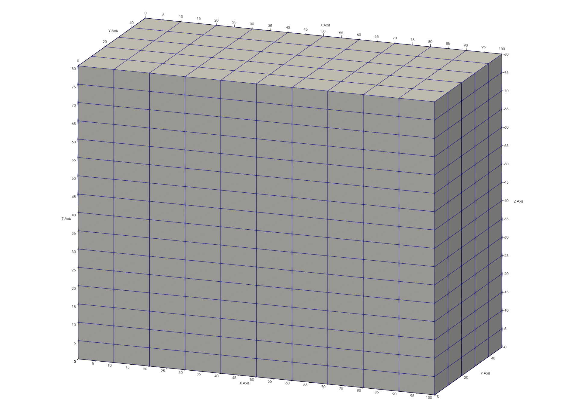
createpts/brick/xyz/ NX NY NZ / XMIN YMIN ZMIN/ XMAX YMAX ZMAX / 1,1,1
As shown in the screen report, createpts/brick creates 1122 hex points and 800 hex elements. The connect option should not be used for the brick option because the hex connectivity is created automatically.
Set Materials and Boundary Tags
It is good practice to set materials for nodes (imt) and elements (itetlcr) to 1 before continuing. A 0 value in these arrays will cause some viewers to ignore that point or element. These attributes must be positive non-zero integers.
Note 1,0,0 represents all for node start,stride,end
cmo / setatt / 3dmesh / imt / 1,0,0 / 1
cmo / setatt / 3dmesh / itetclr / 1,0,0 / 1
It is also good practice to reset the itp attribute anytime materials are changed. This attribute indicates which nodes are on the boundary and which are internal and is used in many of the meshing routines.
resetpts/itp
Check the Mesh
View the Mesh Object status, brief version. This report affirms the creation of a 3D hex mesh. The brief option shows the cmo header without all the attributes.
cmo/status/ 3dmesh / brief
View the min max values of the mesh attributes of the coordinates as another check. The keyword -all- or -xyz- can be used to view mesh object attributes.
cmo/printatt/3dmesh/ -xyz- minmax
Check the mesh with the quality command. There should be no negative or zero volumes.
quality
Write the Mesh and View
Write an AVS format mesh file for viewing the mesh. This file can be rendered in certain scientific 3D visualization applications such as Paraview.
Viewing this mesh, you should see something like the image at the top of the page. By default, Paraview will color the mesh by imt values which are all equal to 1.
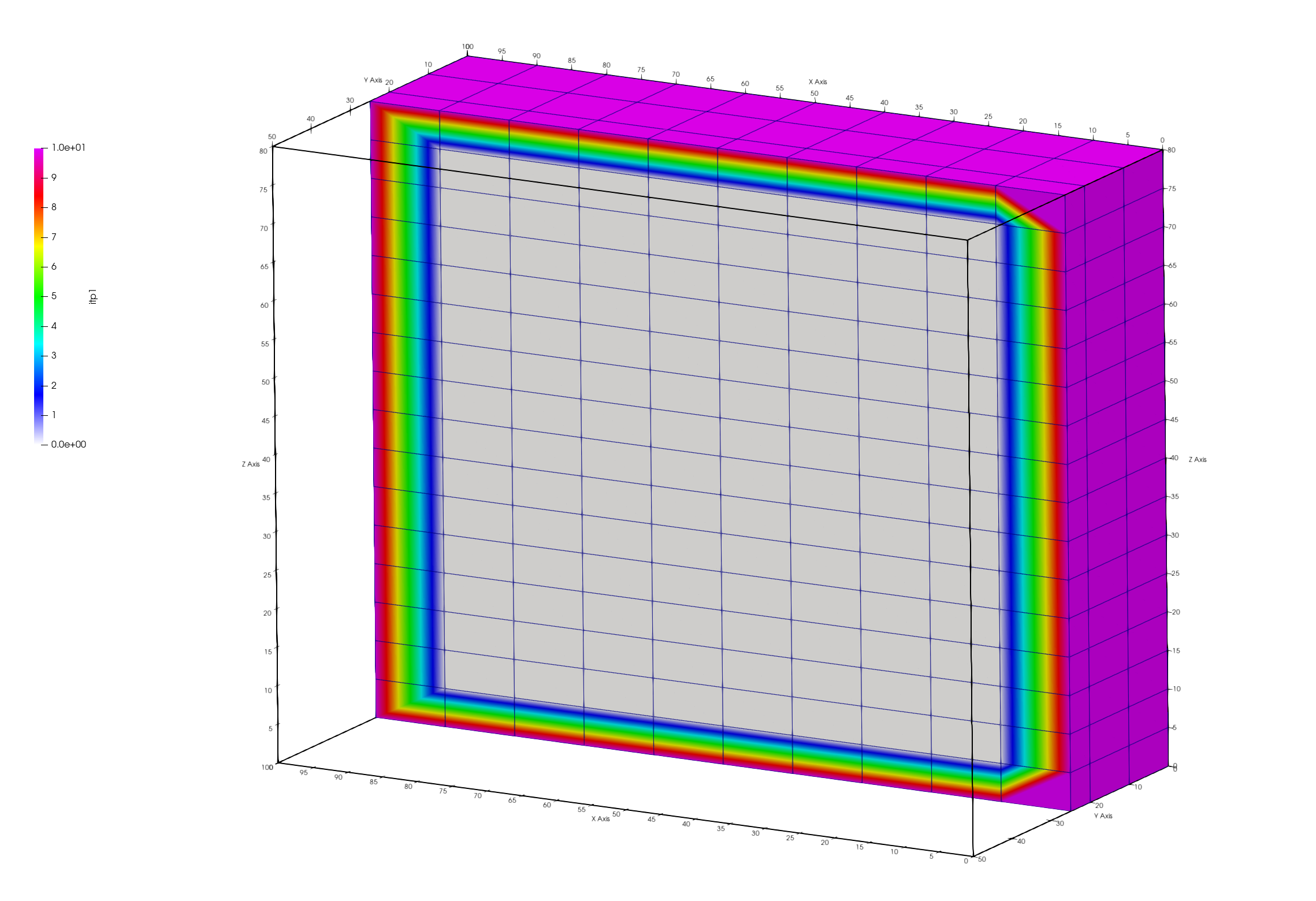
View the mesh using the node attribute itp to see the boundary nodes. The outside nodes will have value of 10 and internal nodes will have value 0. Note when viewing a mesh colored by a node, the colors will “bleed” from one node to the next. Views colored by cell or element will be more distinct.
Image shows hex mesh with node itp colors. The mesh is clipped in half to see the inside nodes of the mesh.
dump/ avs / 01_hex_mesh.inp / 3dmesh
finish
Always end a session or a file with the finish command and a line return after the finish command. The command line parser will not parse a command without a line return.
finish