Step 3. Assign Materials to Hex Mesh and Tet Mesh
LaGriT command file: 03_assign_materials.lgi
LaGriT output file: lagrit.out
LaGriT all run files: Folder step_03
This example will show how to use some basic commands to assign materials to mesh nodes and elements. Interpolation of materials from the hex mesh to the tet mesh is used to ensure block shaped interfaces.
Methods include:
- Set selections using
psetfor mesh points andeltset. - Regions defined by surfaces using
surfaceandregion - Interpolation from hex materials to tet mesh materials using
interpolate - Use LaGriT commands to report material node and element counts for the final mesh
Define Mesh Names
In this example we assign materials (color) to the hex mesh, then interpolate hex mesh materials to the tet mesh. This method ensures nice interfaces between materials. If the tet mesh is colored with following methods, the tet interfaces will be ragged, with tet elements sticking out.
Define input and output file names for easy switch between mesh types. As seen here, the second set of file names are last defined and will be used. If you want to see how it looks to use the tet mesh, simply copy and paste the first 2 lines after the hex file names.
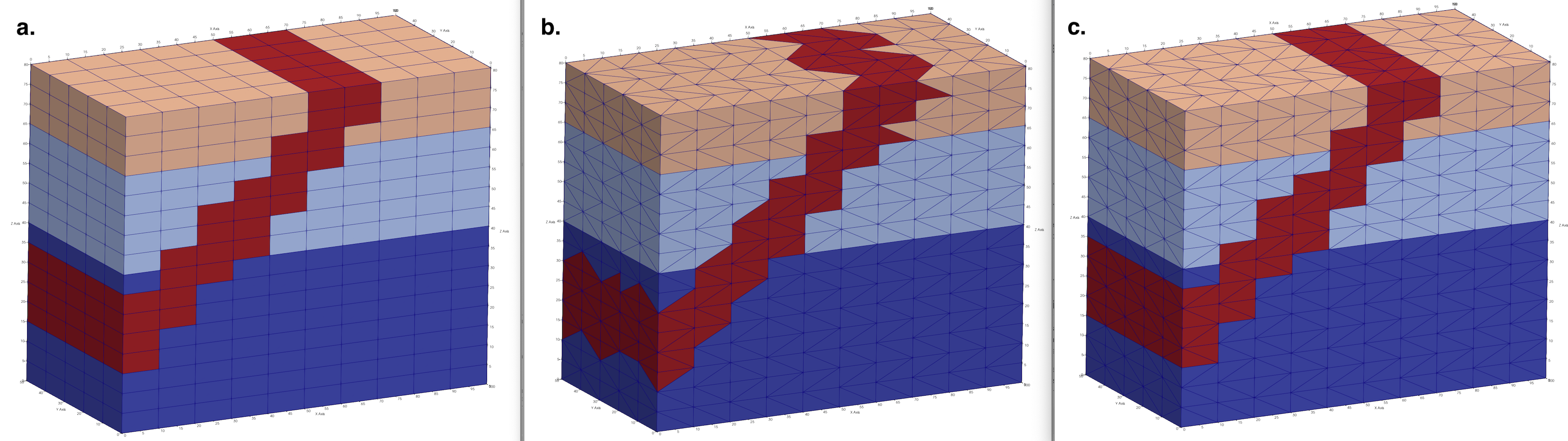
Results are shown in image at top of page. Image a. This example hex_colors.inp b. Run with tet_colors.inp c. This example using interpolation for tet_colors.inp
define IN_FILE 02_tet_mesh.inp
define OUT_FILE tet_colors.inp

define IN_FILE 01_hex_mesh.inp
define OUT_FILE hex_colors.inp
Read the Hex Mesh
We start with the hex mesh created in Step 1. of this tutorial. Instead of creating it again, we just read the AVS mesh file. Note the variable IN_FILE is define above as “01_hex_mesh.inp”. We have given the mesh object the name mo_mat to indicate it is the mesh object we will assign materials to. You can name the mesh anything you want if it is clear and consistent with your usage.
read/avs/ IN_FILE / mo_mat
cmo/status/mo_mat/ brief
cmo/select/mo_mat
Assign Materials by Selected Sets (pset and eltset)
Define some elevations for layers between top and bottom of mesh between 0. and 80.
define MAT1_Ztop 40.
define MAT2_Ztop 62.
For the current mesh, select node sets based on the attribute zic (Z coordinate). Name the psets “pmat1”, “pmat2”, and “pmat3” for use in assigning materials. Note reminder the “1,0,0” refers to node numbers start, stride, stop where “0,0” indicates “all”.
pset/pmat1/attribute zic/1,0,0/ lt MAT1_Ztop
pset/pmat2/attribute zic/1,0,0/ lt MAT2_Ztop
pset/pmat3/attribute zic/1,0,0/ ge MAT2_Ztop
Based on the set selections above, we can now assign integer values to node materials in the imt attribute. In this example ordering of assignment matters as both “pmat1” and “pmat2” overlap below zic=40. This is ok, we simply overwrite by assigning the lowest set last.
cmo/setatt/mo_mat/imt/ pset,get,pmat3 / 3
cmo/setatt/mo_mat/imt/ pset,get,pmat2 / 2
cmo/setatt/mo_mat/imt/ pset,get,pmat1 / 1
To assign materials to the elements, we use the psets above to create element sets. Note elements can be formed to make sure each vertice of the element is in the pset, or such that only one needs to be in the pset. In this example we use inclusive which will include more elements than the exclusive option.
After setting the element sets, assign material integers to the itetclr element attribute in same order as the psets.
eltset/emat1/inclusive/pset,get,pmat1
eltset/emat2/inclusive/pset,get,pmat2
eltset/emat3/inclusive/pset,get,pmat3

cmo/setatt/mo_mat/itetclr/eltset,get,emat3/ 3
cmo/setatt/mo_mat/itetclr/eltset,get,emat2/ 2
cmo/setatt/mo_mat/itetclr/eltset,get,emat1/ 1
Write a temporary file to view node and element colors so far.
dump/ tmp_layers.inp / mo_mat
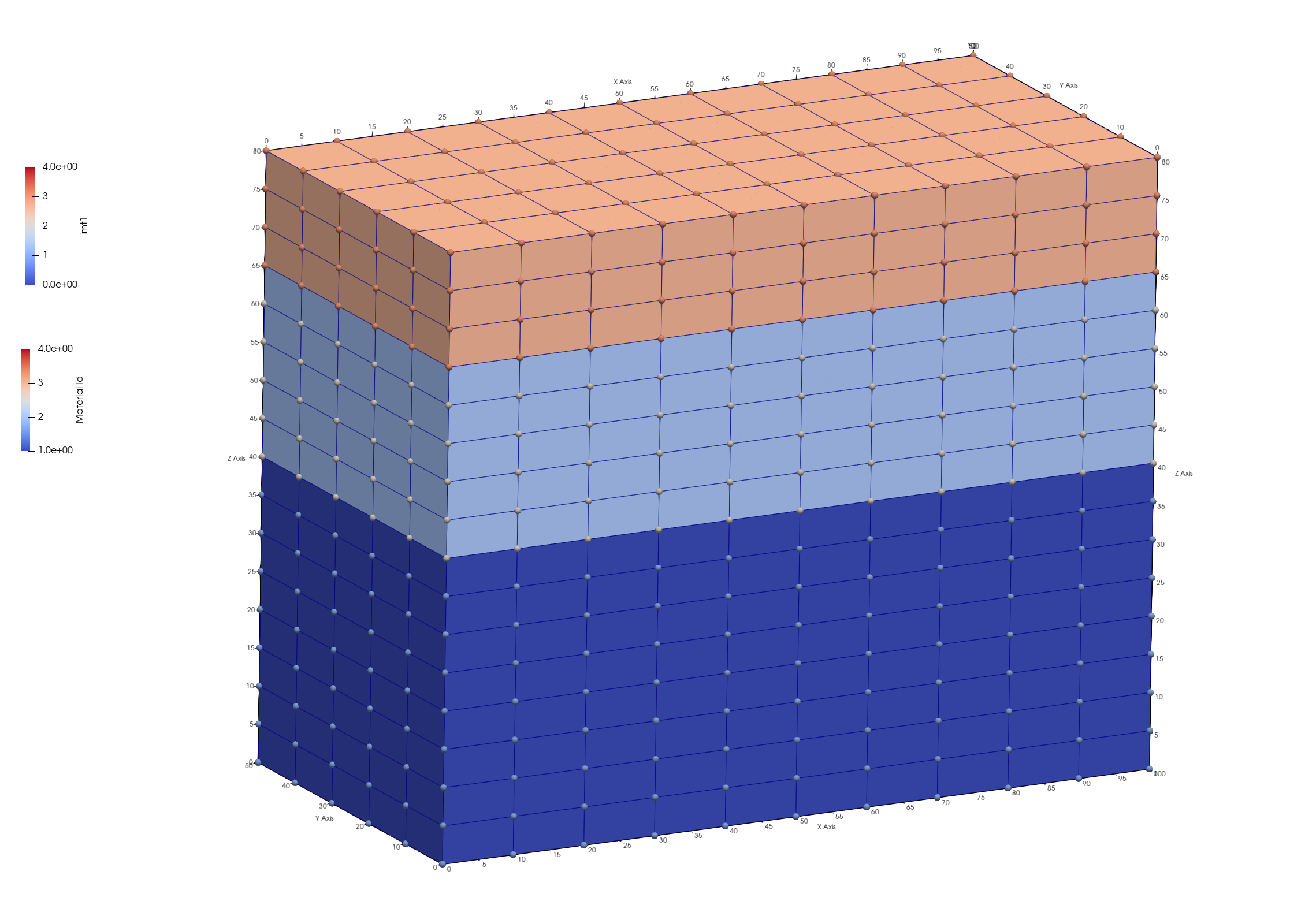
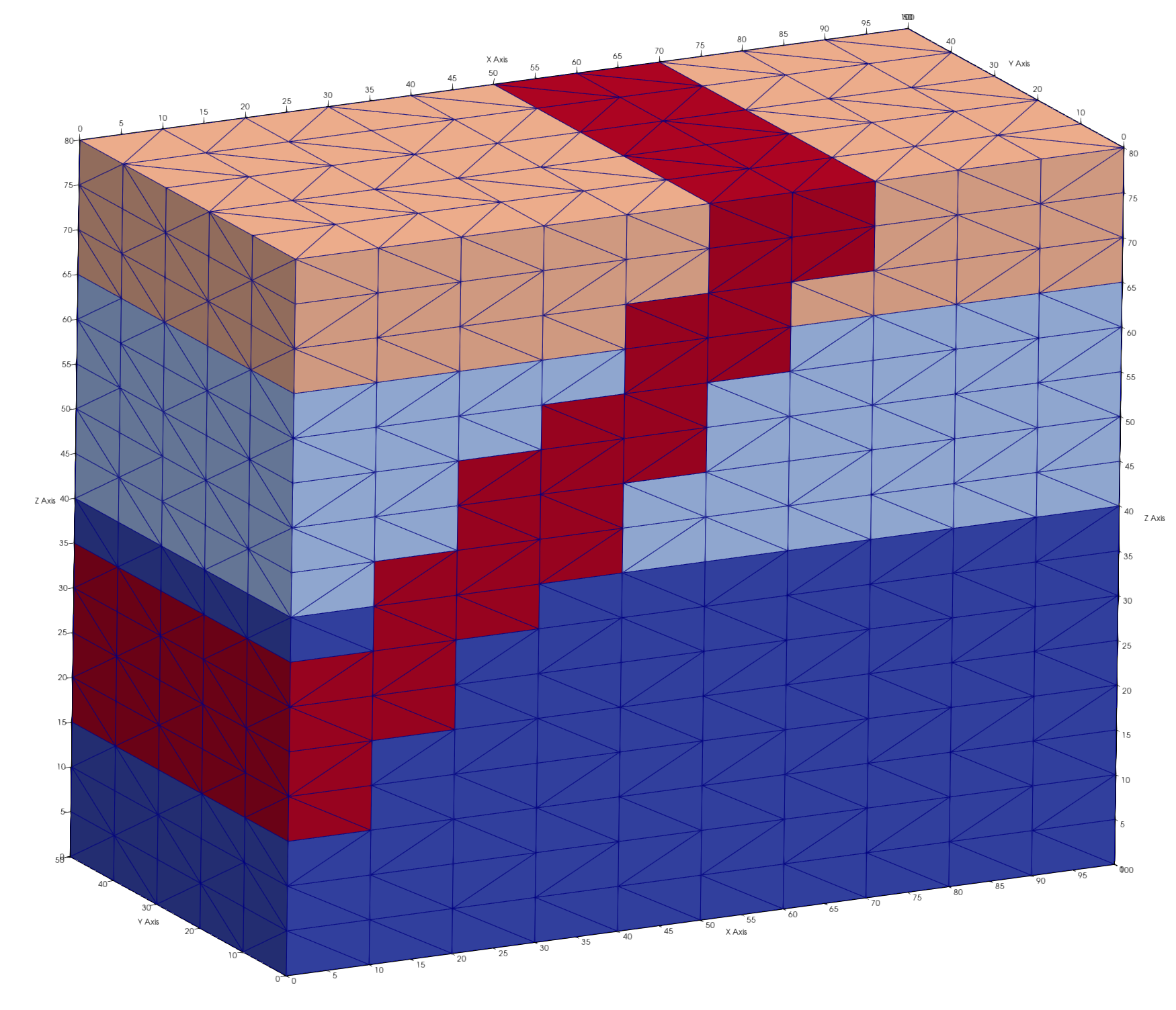
Viewing the mesh file tmp_layers.inp we can check if node imt and element Materials are set as we intended. The result is a mesh with 3 layers with material 1 at the bottom and 3 at the top.
These images were created from Paraview showing the mesh colored by node attribute imt left. The mesh is colored by element materials on the right, mesh nodes colored by imt. Though modeling software such as FEHM use only the node materials, viewing the mesh by element color presents a better picture. Click on images to view full resolution image.

Assign Materials by Surfaces
The region command is extremely useful for defining nodes or elements based on surfaces or geometric shapes. Most of these are represented by their equations, but a surface can also be a mesh that is created or read from file as used in this example. We create two surfaces using surface/sheet//mo_name which will be used to define a region representing a fourth material.
Note. In this case we use a mesh object name that implies it is temporary and will be deleted after use. Creating naming conventions for your objects will help you to keep track of objects during the workflow.
cmo / create / motmp
cmo / select / motmp
Create a quad mesh based on corner coordinates, since this will be used to define regions on the mesh, make sure the surface coordinates extend equal or greater to the mesh. A surface that truncates inside the mesh domain will be ill defined with respect to below or above. These two surfaces could also be created with the surface/plane command and used in the same way, but are internal and can not be viewed with respect to the mesh.
The brick option for createpts is used to create a quad mesh from the point distribution. The quads are converted to triangles with the hextotet command. After the surface is created, print the minmax coordinates and view the surface to make sure it where you want it.
quadxy / 10 5 /-1. -1. 10.   /100.1 -1.  100./ &
               100.1 51. 100./   -1. 51. 10.
createpts/brick/xyz/ 10 5 1 /1,0,0/connect
hextotet/4/ mosurf1 / motmp
cmo / printatt / mosurf1 / -xyz- / minmax
dump/ tmp_surf1.inp / mosurf1
Create a second surface offset from first surface by a distance of 15 in the positive direction.
offsetsurf/ mosurf2 / mosurf1 / 15.
dump/ tmp_surf2.inp / mosurf2
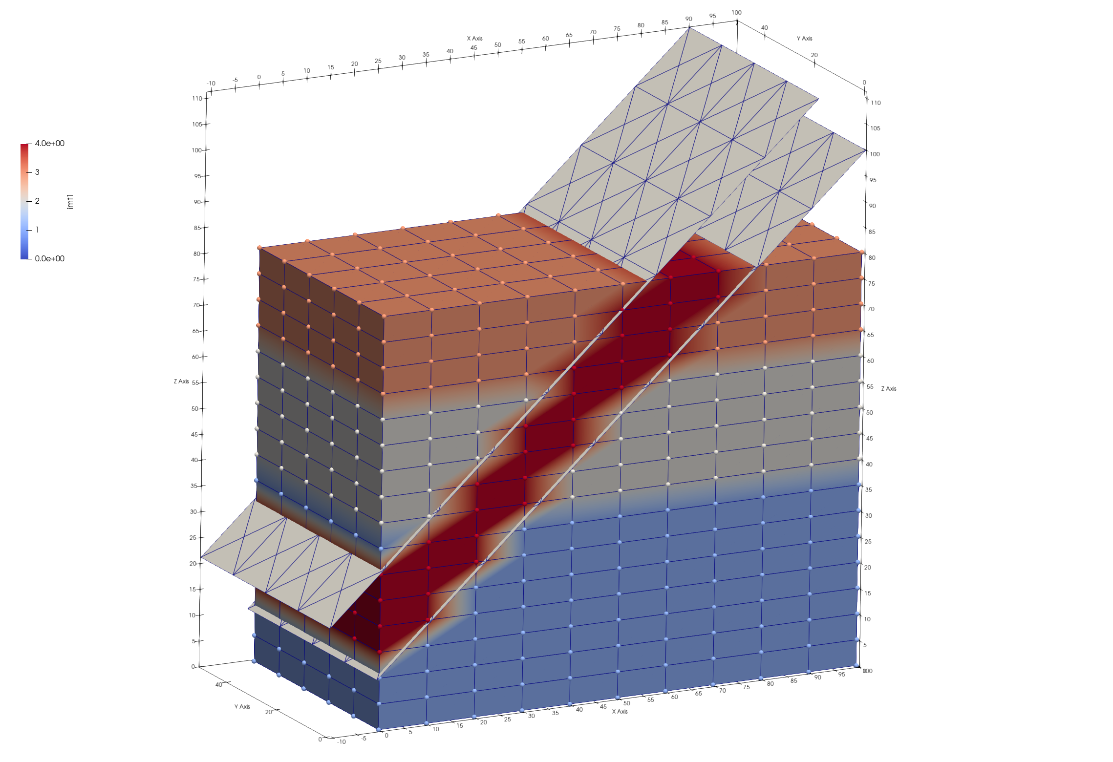
View the mesh and the surfaces together to be sure it is correct. The nodes colored red in the image is the region we will set to material 4.
To use the geometry commands such as surfaces and regions, FIRST make sure your mesh object is current. Otherwise, these geometry command will not be available for use on the mesh object. Use the cmo/select command to make sure you apply these commands to the “mo_mat” mesh object.
In the previous steps we created two mesh objects, mosurf1 and mosurf2. We now tell LaGriT to use those mesh objects to define surfaces of type sheet. There are many types of surfaces such as cone, and box. See more at surface.
cmo / select / mo_mat
surface / s_mosurf1 / reflect / sheet / mosurf1
surface / s_mosurf2 / reflect / sheet / mosurf2
Now that LaGriT has sheets named “s_mosurf1” and “s_mosurf2” defined for the mesh object geometry, we can use them to define a region between the surfaces.
The le and ge operators are used with the region* command to define regions. For instance, ge for a surface means the space on the same side as the surface normal direction, le means the space opposite of the normal direction. Use le, ge to include nodes equal to the surface, otherwise use lt, gt.
region/ r_slant / ge s_mosurf1 and le s_mosurf2
Now use this region named “r_slant” to define node and elements in the slanted region. Use the cmo/setatt command with these sets to assign the value 4 to node imt and element itetclr arrays, but only to the defined sets. The value 4 will overwrite previous values of 1-3 set earlier.
pset/ pslant / region / r_slant
eltset/ eslant / region / r_slant

cmo/ setatt / mo_mat / imt / pset,get,pslant / 4
cmo/ setatt / mo_mat / itetclr / eltset,get,eslant / 4
Since the materials have changed, it is good practice to update the boundary and interface attribute itp mesh arrays. Write the mesh with materials using the “OUT_FILE” variable defined at the beginning.
resetpts/itp
dump / OUT_FILE / mo_mat
cmo / status / mo_mat / brief
Debug hint: things often go wrong early in the script, make sure there are no errors before continuing. You can do this by adding an early finish and observing the output report. If there are no errors reported, and the mesh looks as expected, comment the finish command so the LaGriT command continues.
# Uncomment Early finish to check results
# finish
Assign Materials by Interpolation
If you color the tetrahedral mesh using the above steps, you might get ragged edges that do not look as nice as the colored hex mesh. And if you added refinement to your mesh, using your original coarse hex mesh colors will better preserve the layers as you intended. This will preserve the stair-step interfaces of materials
It is good practice to remove mesh objects that are no longer needed. The more mesh objects that exist, the greater possibility of things getting tangled or mistakes with typos.
cmo/delete/motmp
cmo/delete/mosurf1
cmo/delete/mosurf2
cmo/list
Now that we have a hex mesh with materials the way we like them. Read the computational tetrahedral mesh (from Step 2), and interpolate the hex (source) values to the tet mesh.
read/avs/ 02_tet_mesh.inp / mo_tet
cmo/select/mo_tet
The interpolate/map command copies the value from the enclosing source element to the element (centroid). The interpolate/voronoi command copies the value from the nearest source node to the sink node.
interpolate/map/mo_tet/ itetclr /1,0,0/ mo_mat itetclr
interpolate/voronoi/mo_tet/ imt /1,0,0/ mo_mat imt
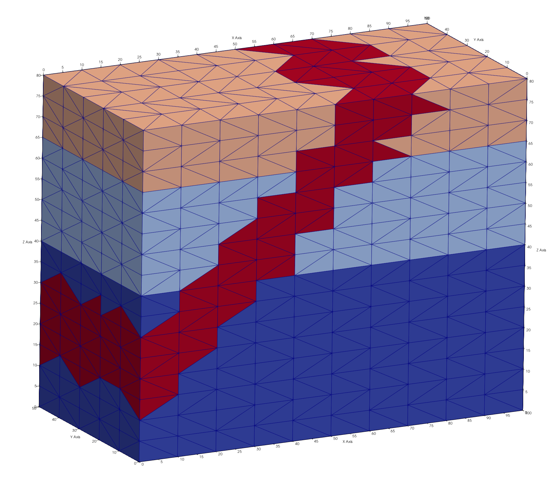
Mesh left shows results if these steps are applied to the tet mesh. Mesh right shows hex mesh interpolated to tet mesh.
Check the interpolated materials with the printatt commands. There should be minmax values 1 and 4.
cmo/printatt/mo_tet/imt minmax
cmo/printatt/mo_tet/itetclr minmax
cmo/printatt/mo_tet/imt minmax
ATTRIBUTE NAME              MIN               MAX         DIFFERENCE    LENGTH
 imt1                             1                4               3      1122

cmo/printatt/mo_tet/itetclr minmax
ATTRIBUTE NAME              MIN               MAX         DIFFERENCE    LENGTH
 itetclr                          1                4               3      4800
Set the boundary nodes based on these new materials and write an AVS mesh file for viewing.
resetpts/itp
dump/avs/tet_interp_materials.inp mo_tet
Report Material Quantities
Sometimes it helps to see node and element material quantities before viewing the mesh. This is a good way to catch easy mistakes. These results are also useful to include in reports as part of the setup description. Scripts can be written to parse “lagrit.out” results for nice tables and other summary information.
The minmax option is a quick easy way to check for mistakes. The imt1 (same as imt) attribute are the node materials, so length of the array is 1122, the number of nodes in this mesh. The itetclr attribute are the element materials with a length of 4800, the number of elements in this mesh. As expected, they both have values from 1 to 4. Note: these material attributes must have integer numbers greater than 0
Note. Unless the tet mesh is modified to be different from the source hex mesh, they will have the same number of nodes. Only the element type and count will change.
cmo/select/mo_tet
cmo/printatt/mo_tet/ imt minmax
cmo/printatt/mo_tet/ itetclr minmax
LaGriT will show the following results.
ATTRIBUTE NAME              MIN               MAX         DIFFERENCE    LENGTH
 imt1                             1                4               3      1122

cmo/printatt/mo_tet/itetclr minmax
ATTRIBUTE NAME              MIN               MAX         DIFFERENCE    LENGTH
 itetclr                          1                4               3      4800
This command will report element volumes by material ID, default is all, but single value reports are an option.
quality/ volume / material
The summary of element volume materials should look like this:
  SUMMARY VOLUME/AREA of ELEMENT COLORS for mo_tet     1      4
...........................................................
Color      Num. Elements   Volume          Fractional Volume
    1        2160          0.1800000E+06     0.450000000
    2        1140          0.9500000E+05     0.237500000
    3         720          0.6000000E+05     0.150000000
    4         780          0.6500000E+05     0.162500000
 Total elements:      4800       Total Volume:  0.4000000E+06
-----------------------------------------------------------
      4800 total elements evaluated.
For modeling applications such as FEHM, the node materials are used, not the elements. This dump/zone_imt command is part of the FEHM commands available to write material zone files. It also creates a good summary of the node materials.
dump/zone_imt/ tet / mo_tet
The summary of node counts by material will look like this:
*********dump_material_lists********
Minimum material ID value =      1
Maximum material ID value =      4
Total possible materials  =      4
Material       1 has       468 nodes. #nodes/nnodes is   0.417112290859
Material       2 has       270 nodes. #nodes/nnodes is   0.240641713142
Material       3 has       204 nodes. #nodes/nnodes is   0.181818187237
Material       4 has       180 nodes. #nodes/nnodes is   0.160427808762
We do not currently have an easy wrapper command for a summary of voronoi volumes, but a summary can be generated by using the following commands.
- Use the command
cmo/addattto create a node attribute with values of voronoi volumes for each node. - Create a pset for each material value.
- Use the
mathcommand to sum all voronoi values in the indicated pset,get,p1 set of nodes.
Note: the loop command can be used to loop through each of the material values.
cmo addatt/mo_tet/vor_volume/vorvol
pset/p1/attribute/imt/1,0,0/ eq 1
math/sum/mo_tet/vol_tot/pset,get,p1/mo_tet/vorvol
pset/p1/attribute/imt/1,0,0/ eq 2
math/sum/mo_tet/vol_tot/pset,get,p1/mo_tet/vorvol
pset/p1/attribute/imt/1,0,0/ eq 3
math/sum/mo_tet/vol_tot/pset,get,p1/mo_tet/vorvol
pset/p1/attribute/imt/1,0,0/ eq 4
math/sum/mo_tet/vol_tot/pset,get,p1/mo_tet/vorvol
There will be some extra LaGriT output during the run including “AMatbld3d_stor” output regarding the voronoi volumes and associated coefficients. Extra lines can be removed for a summary that looks like this:
AMatbld3d_stor: Volume min =   6.2500000E+01
AMatbld3d_stor: Volume max =   5.0000000E+02
AMatbld3d_stor: Total Volume:   4.0000000E+05

 THE PSET  p1  HAS        468 POINTS
vorvol sum =   0.167500000000E+06

 THE PSET  p1  HAS        270 POINTS
vorvol sum =   0.100000000000E+06

 THE PSET  p1  HAS        204 POINTS
vorvol sum =   0.650000000000E+05

 THE PSET  p1  HAS        180 POINTS
vorvol sum =   0.675000000000E+05
finish
Always end a session or a file with the finish command and a line return after the finish command. The command line parser will not parse a command without a line return.
finish